
Radio frequency network

a radio frequency network and frequency technology, applied in frequency-division multiplexes, electrical equipment, wireless commuication services, etc., can solve the problems of low-priced technology used in amplifiers and loss dependence, and achieve sufficient coverage, optimize the dynamic range of the network, and save the cost of monitoring equipment and maintenance personnel for commissioning and testing.

Active Publication Date: 2013-04-23
RFS TECH INC
View PDF10 Cites 211 Cited by
  • Summary
  • Abstract
  • Description
  • Claims
  • Application Information

AI Technical Summary

Benefits of technology

[0013]The automatic self-leveling units according to the present invention provide for an automatic self-leveling functionality over the whole network structure. In particular, it is possible to automatically compensate for RF network losses, to avoid an over-drive if the number of RF carriers is increased, and to avoid intermodulations. In addition, network extensions in size can be achieved easily, since new amplifier modules adopt additional RF losses automatically. Thus, the present invention provides for a new type of cost-efficient solution of active RF networks, which can be used in plug-and-play function during commissioning. In particular, an effort for installation, commissioning, and any modification of the system is minimized, because time consuming manual leveling of the system is not required. In addition, the present invention enables an increase of high frequency carriers.
[0019]Usually, any adaptation or upgrade of the network to new conditions and / or settings only impacts the architecture of active system elements. The wired distribution system needs not to be changed. Thus, the self-leveling plug-and-play system according to the present invention is more flexible and consequently more cost-effective in comparison with known system architectures.

Problems solved by technology

Furthermore, low-priced technology can be used in the amplifiers, since the high frequency energy is generated directly at the antennas.
The wired distribution system attenuates this power level and the loss is dependent on the network architecture.

Method used


Image

  • Radio frequency network
  • Radio frequency network
  • Radio frequency network

Examples


Embodiment Construction

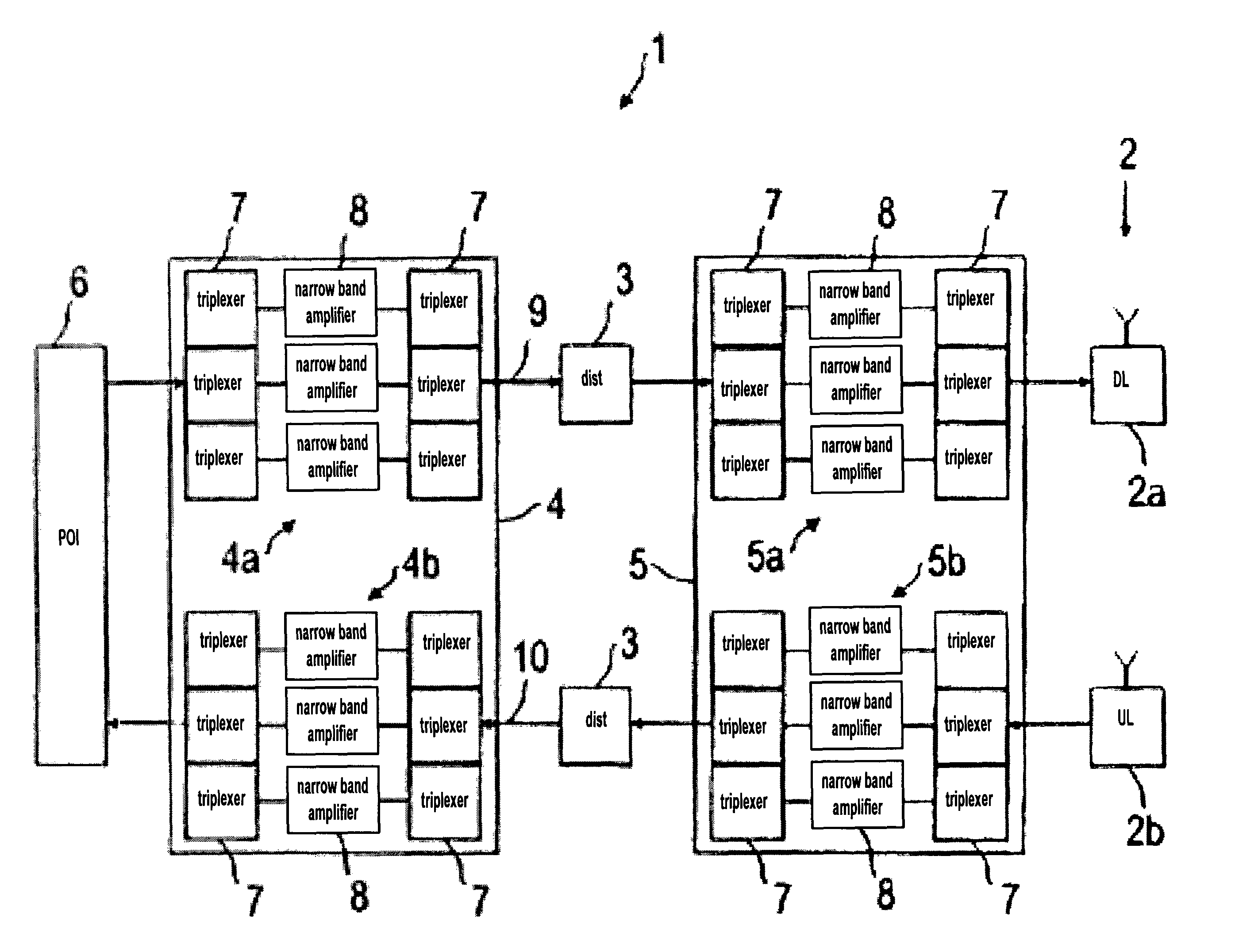
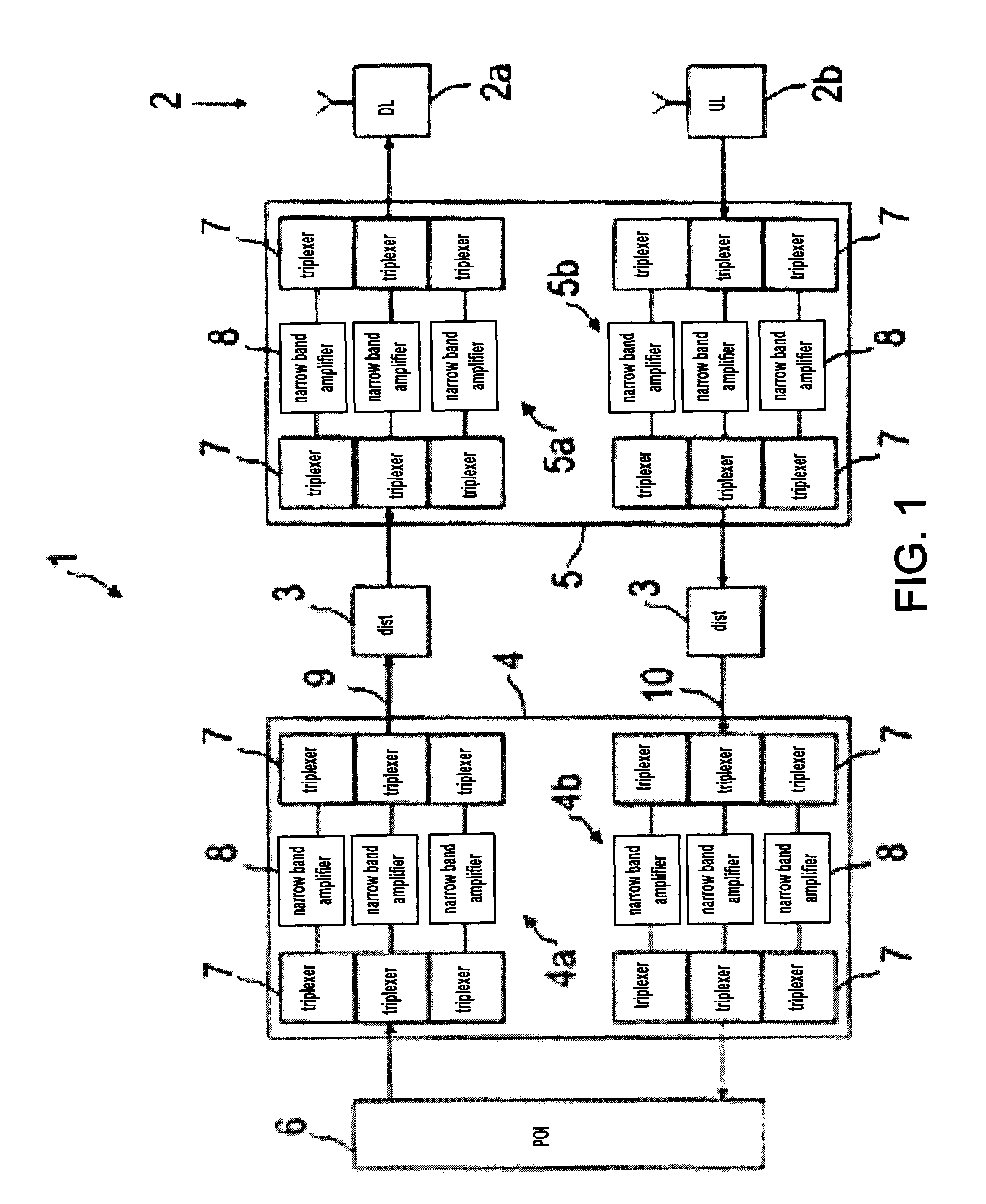
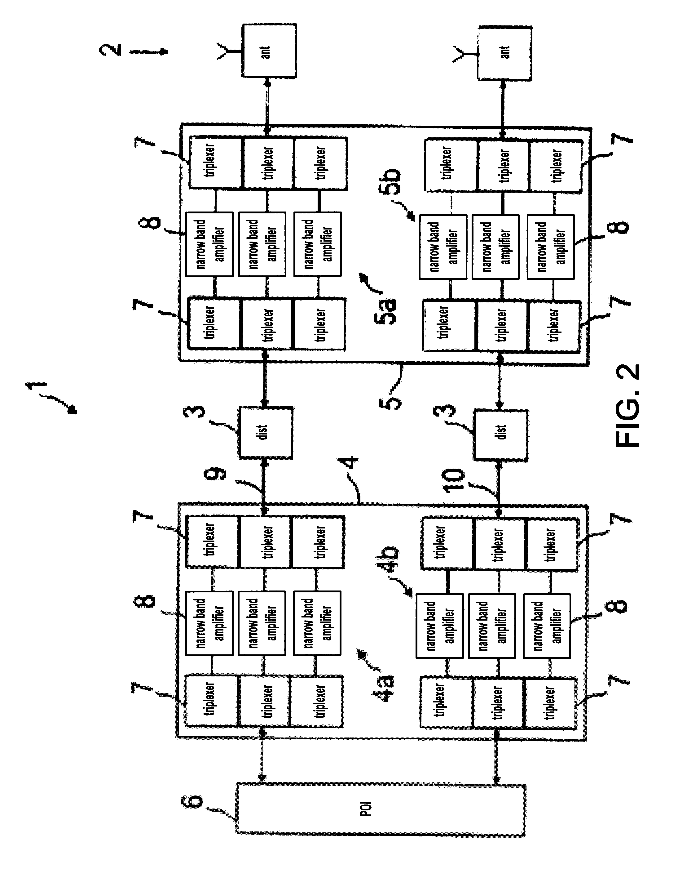
[0024]FIG. 1 shows a block diagram of a first embodiment of a radio frequency network 1 according to the present invention. The radio frequency network 1 comprises a distributed antenna system 2 having radiating elements (not shown) and a wired distribution system 3 feeding the distributed antenna system 2. Furthermore, the shown radio frequency network 1 comprises a line amplifier 4 at one end of the wired distribution system 3 and an antenna amplifier 5 at the other end thereof. Signals from a centralized source (not shown), e.g. Base Transceiver Station (BTS) or Node B or off-air repeater, are combined via a point of interconnection 6 (POI) and fed to the wired distribution system 3 via the line amplifier 4. The radio frequency network 1 shown in FIG. 1 is bidirectional. That is, signals received by the distributed antenna system 2 are transmitted via the antenna amplifier 5, the wired distribution system 3, and the line amplifier 4 to the point of interconnection 6.

[0025]The rad...


PUM


Abstract

The present invention relates to radio frequency (RF) distribution systems for mobile communications. In particular, the present invention relates to a radio frequency network facilitating radio communication where the usual free space propagation of electromagnetic waves is hampered, undesired or impossible, for example in tunnels, mines, and buildings and in large complexes like exhibition grounds, shopping malls, and airports. The radio frequency network comprises a distributed antenna system having radiating elements, a wired distribution system feeding the distributed antenna system, at least one antenna amplifier between one end of the wired distribution system and the distributed antenna system, at least one line amplifier at the other end of the wired distribution system, and automatic self-leveling units included in the antenna and line amplifiers.

Description

[0001]The invention is based on a priority application EP 08 290 805.4 which is hereby incorporated by reference.TECHNICAL FIELD[0002]The present invention relates to radio frequency (RF) distribution systems for mobile communications. In particular, the present invention relates to a radio frequency network facilitating radio communication where the usual free space propagation of electromagnetic waves is hampered, undesired or impossible, for example in tunnels, mines, and buildings and in large complexes like exhibition grounds, shopping malls, and airports.BACKGROUND OF THE INVENTION[0003]In this regard, WINS is a known term. WINS stands for Wireless Indoor Solutions offering to customers RF communication systems for confined areas. It enables users to use their mobile radios and cellular phones in areas normally not covered with RF signals. The aim of such communication systems is to distribute cellular services using a cost-efficient and broadband infrastructure, wherein the d...

Claims


Application Information

Patent Timeline
Patent Type & Authority Patents(United States)
IPC IPC(8): H04W4/00
CPCH04W88/085
Inventor HETTSTEDT, HEINZ-DIETERZORAD, ROBERTSCHROEDER, AXELKLAUKE, GERDSCHOMBURG, EKKEHARD
Owner RFS TECH INC
Learn More