Radio frequency network

a radio frequency network and frequency technology, applied in frequency-division multiplexes, electrical equipment, wireless commuication services, etc., can solve the problems of low-priced technology used in amplifiers and loss dependence, and achieve sufficient coverage, optimize the dynamic range of the network, and save the cost of monitoring equipment and maintenance personnel for commissioning and testing.

Active Publication Date: 2010-03-04
ALCATEL LUCENT SAS
View PDF7 Cites 33 Cited by
  • Summary
  • Abstract
  • Description
  • Claims
  • Application Information

AI Technical Summary

Benefits of technology

[0014]According to a preferred embodiment of the present invention the automatic self-leveling units are adapted to provide a fixed output signal level for a received signal level range. Preferably, the dynamic range of the automatic self-leveling units and their reaction time can be initially adjusted to each other so that the whole network operates in a balanced way providing defined signal levels at the amplifier outputs. Thus, within a certain signal range at the input of the self-leveling units, no commissioning and testing effort is necessary every time a network parameter is changed, e.g. a new signal carrier is introduced, or aging and temperature effects cause a signal loss or gain. Once the radio frequency network has been installed and set into operation, costly monitoring equipment and maintenance personnel for commissioning and testing can be saved.
[0015]Basically, the antenna amplifier amplifies uplink and downlink signals. Download signals are amplified in order to provide sufficient coverage for a dedicated coverage area. Furthermore, the antenna amplifier provides for compensation of losses of the wired distribution system in download and low noise amplification of uplink signals. An automatic self-leveling unit of the antenna amplifier provides a limiting function in uplink in order to protect the whole radio frequency network against non-linear signals resulting from high input power levels. In particular, in uplink the dynamic range is automatically optimized, since incoming power levels from different distributed antenna systems are adjusted to a constant value. Furthermore, low-priced technology can be used in the amplifiers, since the high frequency energy is generated directly at the antennas. In contrast thereto, prior art systems require high-level technology in concentrated amplifiers or base stations at the entry of the network. The line amplifier optimizes the dynamic range of the network and compensates for RF losses resulting from the passive distribution system independently of the distribution. Furthermore, in downlink the line amplifier provides for automatic and independent leveling of the antenna amplifier in order to level the input signals from each path to an equal output power level resulting in a maximized and constant dynamic range. In addition, in downlink the line amplifier increases a power level of an input signal to a constant output power level. The wired distribution system attenuates this power level and the loss is dependent on the network architecture. The automatic level control inside the antenna amplifier compensates for the loss of the distribution system and produces a constant output power level. Thus, in combination with a line amplifier compensating passive losses of the distribution system a plug-and-play system operation is guaranteed.
[0016]According to a furthe

Problems solved by technology

Furthermore, low-priced technology can be used in the amplifiers, since the high frequency energy is generated directly at t

Method used


Image

  • Radio frequency network
  • Radio frequency network
  • Radio frequency network

Examples


Embodiment Construction

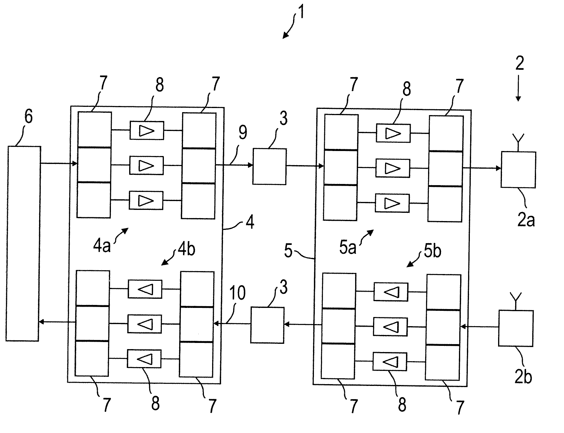
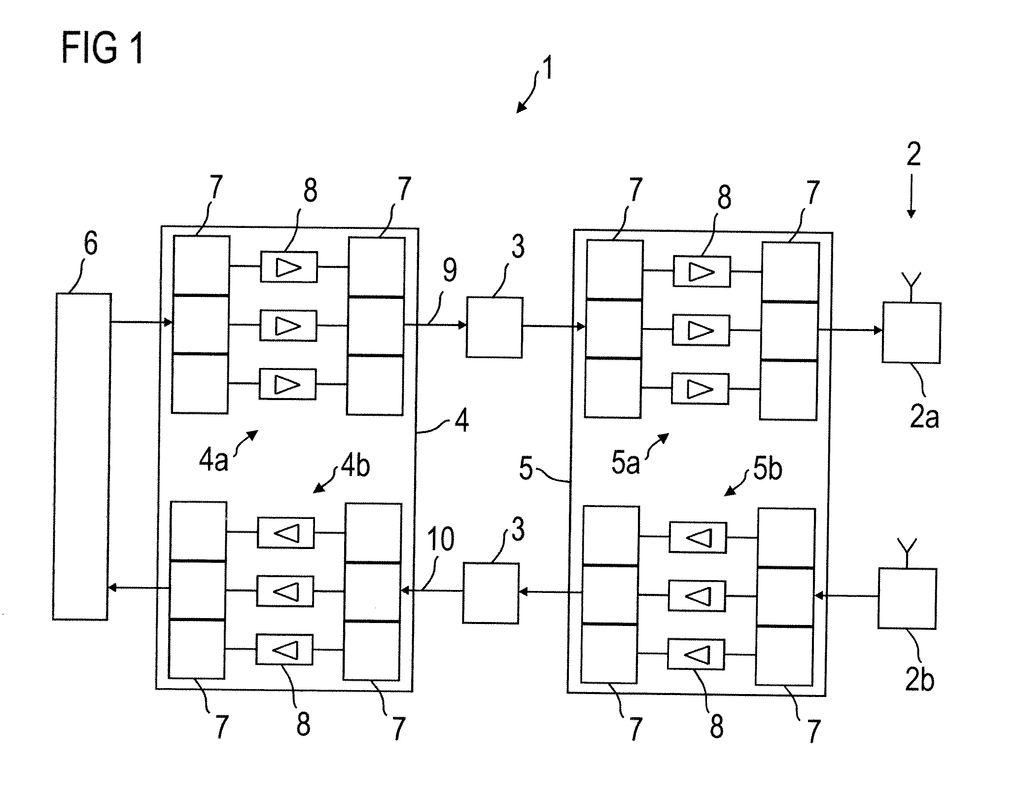
[0024]FIG. 1 shows a block diagram of a first embodiment of a radio frequency network 1 according to the present invention. The radio frequency network 1 comprises a distributed antenna system 2 having radiating elements (not shown) and a wired distribution system 3 feeding the distributed antenna system 2. Furthermore, the shown radio frequency network 1 comprises a line amplifier 4 at one end of the wired distribution system 3 and an antenna amplifier 5 at the other end thereof. Signals from a centralized source (not shown), e.g. Base Transceiver Station (BTS) or Node B or off-air repeater, are combined via a point of interconnection 6 (POI) and fed to the wired distribution system 3 via the line amplifier 4. The radio frequency network 1 shown in FIG. 1 is bidirectional. That is, signals received by the distributed antenna system 2 are transmitted via the antenna amplifier 5, the wired distribution system 3, and the line amplifier 4 to the point of interconnection 6.

[0025]The rad...


PUM


Abstract

The present invention relates to radio frequency (RF) distribution systems for mobile communications. In particular, the present invention relates to a radio frequency network facilitating radio communication where the usual free space propagation of electromagnetic waves is hampered, undesired or impossible, for example in tunnels, mines, and buildings and in large complexes like exhibition grounds, shopping malls, and airports. The radio frequency network (1) comprises a distributed antenna system (2) having radiating elements, a wired distribution system (3) feeding the distributed antenna system (2), at least one antenna amplifier (5) between one end of the wired distribution system (3) and the distributed antenna system (2), at least one line amplifier (4) at the other end of the wired distribution system (3), and automatic self-leveling units included in the antenna and line amplifiers (4, 5).

Description

[0001]The invention is based on a priority application EP 08 290 805.4 which is hereby incorporated by reference.TECHNICAL FIELD[0002]The present invention relates to radio frequency (RF) distribution systems for mobile communications. In particular, the present invention relates to a radio frequency network facilitating radio communication where the usual free space propagation of electromagnetic waves is hampered, undesired or impossible, for example in tunnels, mines, and buildings and in large complexes like exhibition grounds, shopping malls, and airports.BACKGROUND OF THE INVENTION[0003]In this regard, WINS is a known term. WINS stands for Wireless Indoor Solutions offering to customers RF communication systems for confined areas. It enables users to use their mobile radios and cellular phones in areas normally not covered with RF signals. The aim of such communication systems is to distribute cellular services using a cost-efficient and broadband infrastructure, wherein the d...

Claims


Application Information

Patent Timeline
IPC IPC(8): H04J1/00
CPCH04W88/085
Inventor HETTSTEDT, HEINZ-DIETERZORAD, ROBERTSCHROEDER, AXELKLAUKE, GERDSCHOMBURG, EKKEHARD
Owner ALCATEL LUCENT SAS
Why Eureka
Try Eureka