Hub unit manufacturing method and hub unit

a manufacturing method and hub technology, applied in the direction of manufacturing tools, bearing unit rigid support, transportation and packaging, etc., can solve the problems of obstructing the production time of the hub unit, requiring a large amount of measurement time, and reducing the manufacturing cost, so as to facilitate the setting of a prescribed preload or an axial gap, small number, and small assembly cycle time

Active Publication Date: 2013-04-30
JTEKT CORP
View PDF25 Cites 1 Cited by
  • Summary
  • Abstract
  • Description
  • Claims
  • Application Information

AI Technical Summary

Benefits of technology

[0005]It is an object of the present technology to provide a hub unit manufacturing method and a hub unit, which is able to easily set a prescribed preload or an axial gap even when the manufacturing size of the parts are not highly accurate and has a small number of assembling steps, a small assembly cycle time and a large extraction rate. A particular object of the present technology is to provide a hub unit manufacturing method capable of remarkably improving the accuracy in axial gap.

Problems solved by technology

So, a great deal of time is necessary for the measurements and there is obstructive in shortening the production time of the hub unit and reducing the manufacturing cost.Patent Document 1: JP H02-159536 A

Method used


Image

  • Hub unit manufacturing method and hub unit
  • Hub unit manufacturing method and hub unit
  • Hub unit manufacturing method and hub unit

Examples


Embodiment Construction

[0060]The present technology will be described in detail below by the embodiments shown in the drawings.

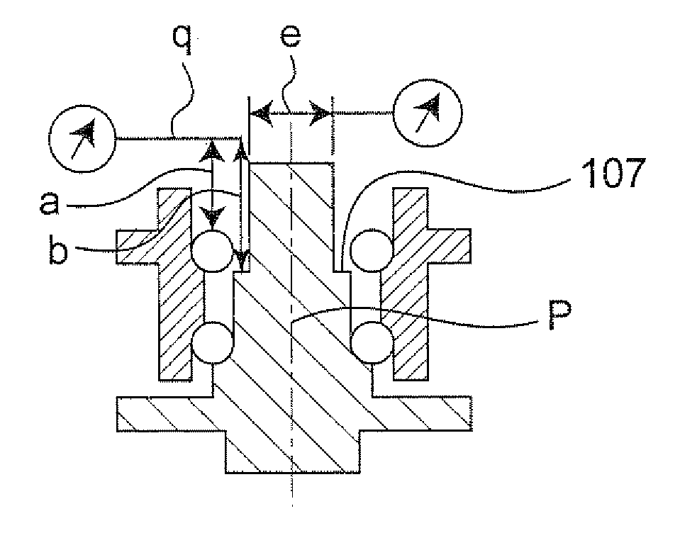
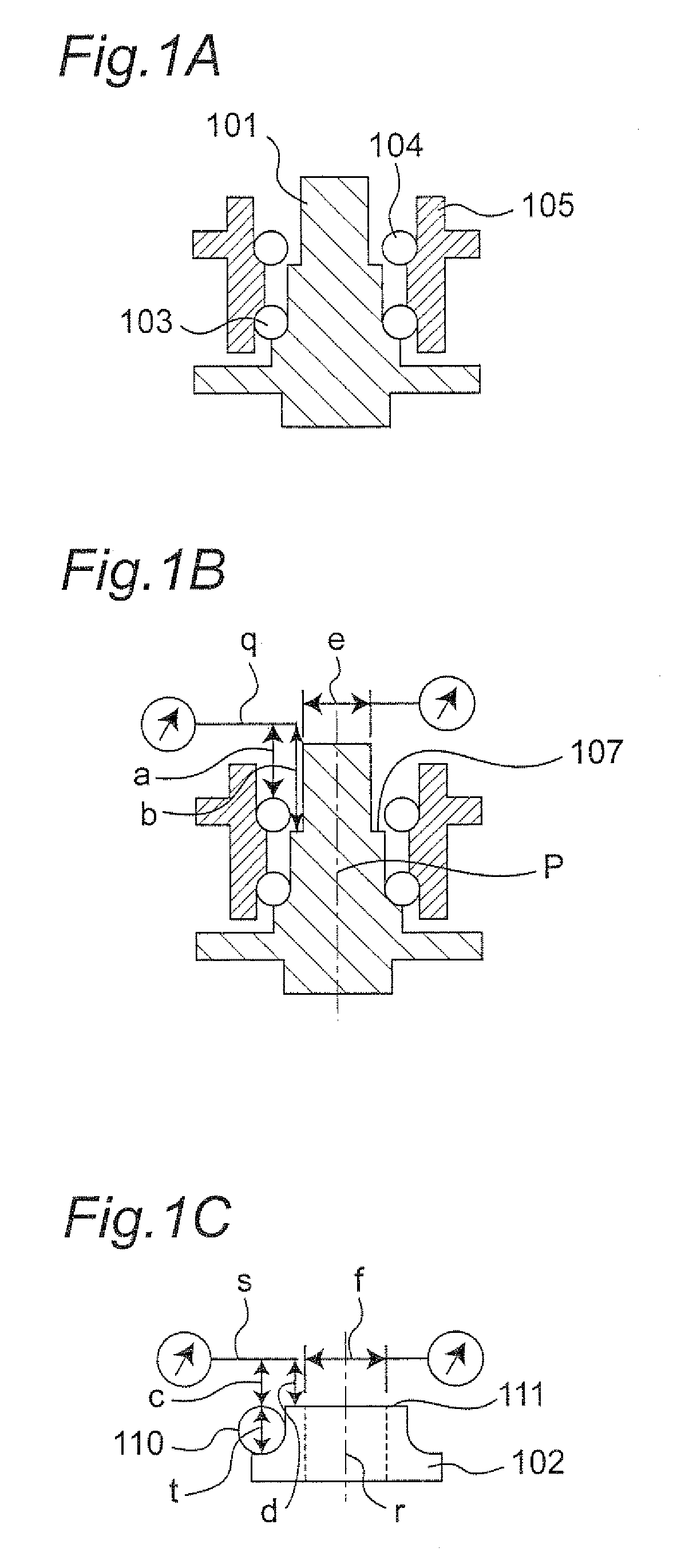
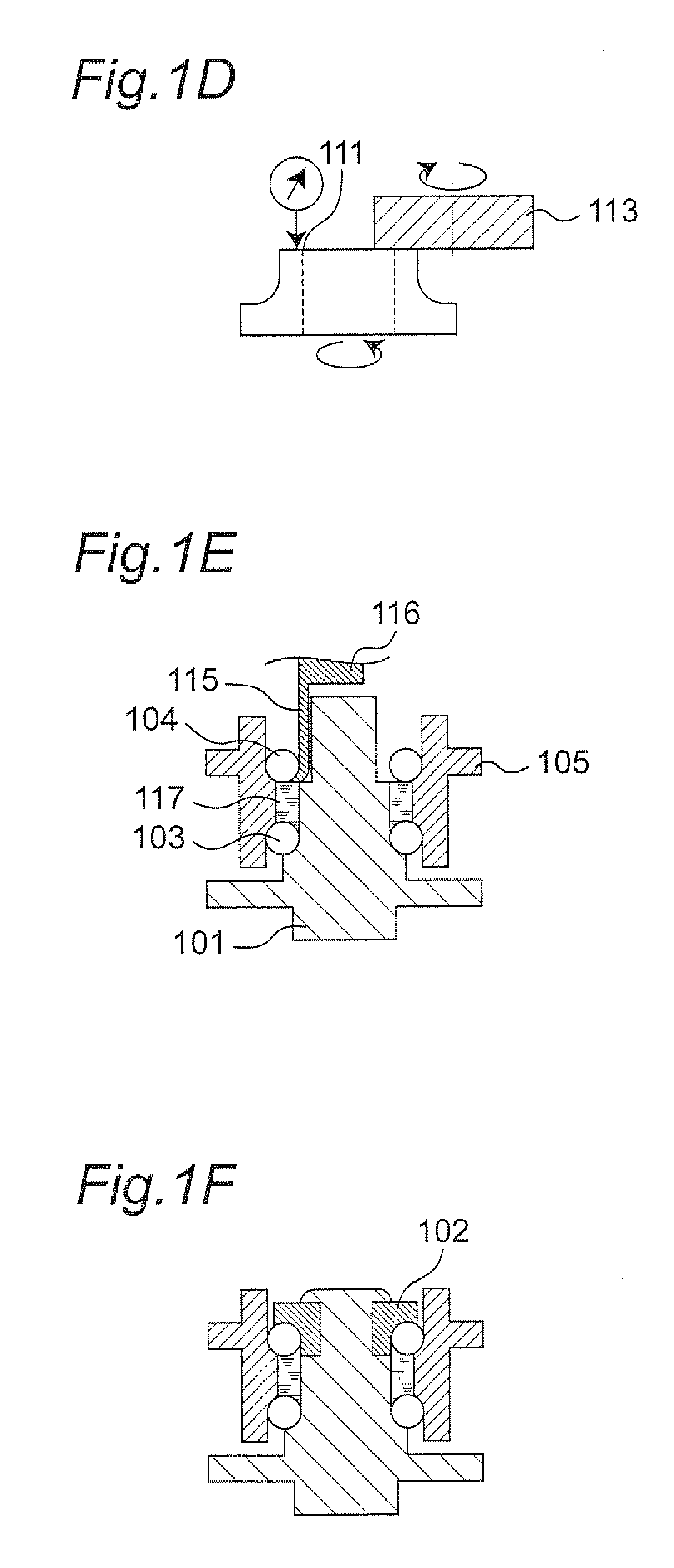
[0061]FIGS. 1A through 1F are views for explaining the hub unit manufacturing method of one embodiment of the present technology.

[0062]The hub unit manufacturing method of the one embodiment of the present technology is described below with reference to FIGS. 1A through 1F. In FIGS. 1A through 1F, 101 indicates a shaft, 102 indicates an inner ring, 103 indicates a first ball as one example of the first rolling element, 104 indicates a second ball as one example of the second rolling element and 105 indicates an outer ring.

[0063]First of all, a subassembly step is carried out. In the subassembly step, the shaft 101, the outer ring 105, the first ball 103 and the second ball 104 are assembled so that the first ball 103 is assembled in between the outer peripheral raceway surface of the shaft 101 and a first inner peripheral raceway surface of the outer ring 105, and the second ball ...


PUM

PropertyMeasurementUnit
diameteraaaaaaaaaa
expansion angleaaaaaaaaaa
diameteraaaaaaaaaa

Abstract

In a state in which a first ball 103 is assembled in between a first inner peripheral raceway surface of an outer ring 105 and an outer peripheral raceway surface of a shaft 101, and a second ball 104 is placed in between a second inner peripheral raceway surface of the outer ring 105 and an outer peripheral surface of the shaft 101, a first distance “a” from a plane “q” generally perpendicular to a central axis “p” of the shaft 101 to the second ball 104 and a second distance “b” from the plane “q” to a stepped portion 107 of the shaft 101 are measured. Then, the size in the axial direction of the inner ring 102 is adjusted on the basis of a difference between the first distance “a” and the second distance “b”.

Description

[0001]This application is the U.S. national phase of International Application No. PCT / JP2007 / 050661, filed Jan. 18, 2007, which designated the U.S. and claims priority to Japan Application No. 2006-012776, filed Jan. 20, 2006, and Japan Application No. 2006-013277, filed Jan. 23, 2006, the entire contents of each of which are hereby incorporated by reference.TECHNICAL FIELD[0002]The present technology relates to a hub unit manufacturing method and a hub unit and, in particular, to the third-generation hub unit manufacturing method for mounting an inner ring on one end side of a shaft placed inside the inner periphery of an outer ring and the third-generation hub unit.BACKGROUND ART[0003]Conventionally, when a hub unit is manufactured by assembling a shaft, an inner ring, balls and an outer ring, it is necessary to measure the sizes of the each part in order to cope with variations in the measurement accuracy of the shaft, variations in the measurement accuracy of the inner ring, va...

Claims


Application Information

Patent Timeline
Patent Type & Authority Patents(United States)
IPC IPC(8): B21K1/40B21D53/10F16C35/00
CPCB60B27/0005B60B27/0094F16C19/186F16C43/04F16C2326/02F16C2229/00F16C2226/60Y10T29/49689Y10T29/4968Y10T29/49682Y10T29/49535Y10T29/49684Y10T29/49771Y10T29/49702F16C2226/36
Inventor MIURA, HIROYUKIYOSHIKAWA, HIROSHIOHTANI, YASUHIRO
Owner JTEKT CORP
Why Eureka
Try Eureka