
Field olfactometer with differential flow-based dynamic dilution

a dynamic dilution and field olfactometer technology, applied in the direction of instruments, volume/mass flow by dynamic fluid flow effect, measurement devices, etc., can solve the problems of inability to widely distribute devices, high cost of laboratory-based olfactometry, and inability to achieve widespread distribution, etc., to achieve convenient calibration of the filter cartridge assembly, reduce cost, and be inexpensive to produce

Inactive Publication Date: 2013-04-30
DON WRIGHT & ASSOC L L C
View PDF13 Cites 11 Cited by
  • Summary
  • Abstract
  • Description
  • Claims
  • Application Information

AI Technical Summary

Benefits of technology

The present invention provides an olfactometer and method of olfactomy that has several advantages over prior field olfactometers and olfactomy methods. First, the device produces a positive indication when it reaches a target flow rate, making it easy to determine if an odor is present in ambient air at a given dilution ratio. Second, the device has an integrated filter body and sample air path, allowing for calibration of the filter cartridge assembly independently of the remainder of the olfactometer, resulting in fine-tuned flow paths for each replacement filter cartridge and sample flow path. Third, the device is relatively inexpensive to produce and easy to use, making it suitable for wide distribution and more complete assessment of odors emanating from a given odor source.

Problems solved by technology

However, laboratory-based olfactometry is expensive and thus impractical for many applications.
There are a number of problems encountered with the prior art field olfactometers.
First, the prior art field olfactometers are relatively expensive and thus the devices cannot be widely distributed to allow assessment of odors over large geographical areas and over extended periods of time encompassing a range of environmental conditions.
This is a very serious drawback because odor plumes tend to be transient in nature and are variable with weather conditions.
Also, with the Box Scentometer and Mask Scentometer, it is difficult to ensure that the nasal inhalation by the user is sufficient to produce the desired flow rate through the two flow paths of the device to result in the intended dilution ratio between diluent air and sample air.
Even with the Nasal Ranger olfactometer, which incorporates a flow meter, it is difficult for the user to coordinate their observation of the meter with their operation of the device to ensure that the flow rate through the device is at a level to produce the desired dilution ratio.

Method used


Image

  • Field olfactometer with differential flow-based dynamic dilution
  • Field olfactometer with differential flow-based dynamic dilution
  • Field olfactometer with differential flow-based dynamic dilution

Examples


Embodiment Construction

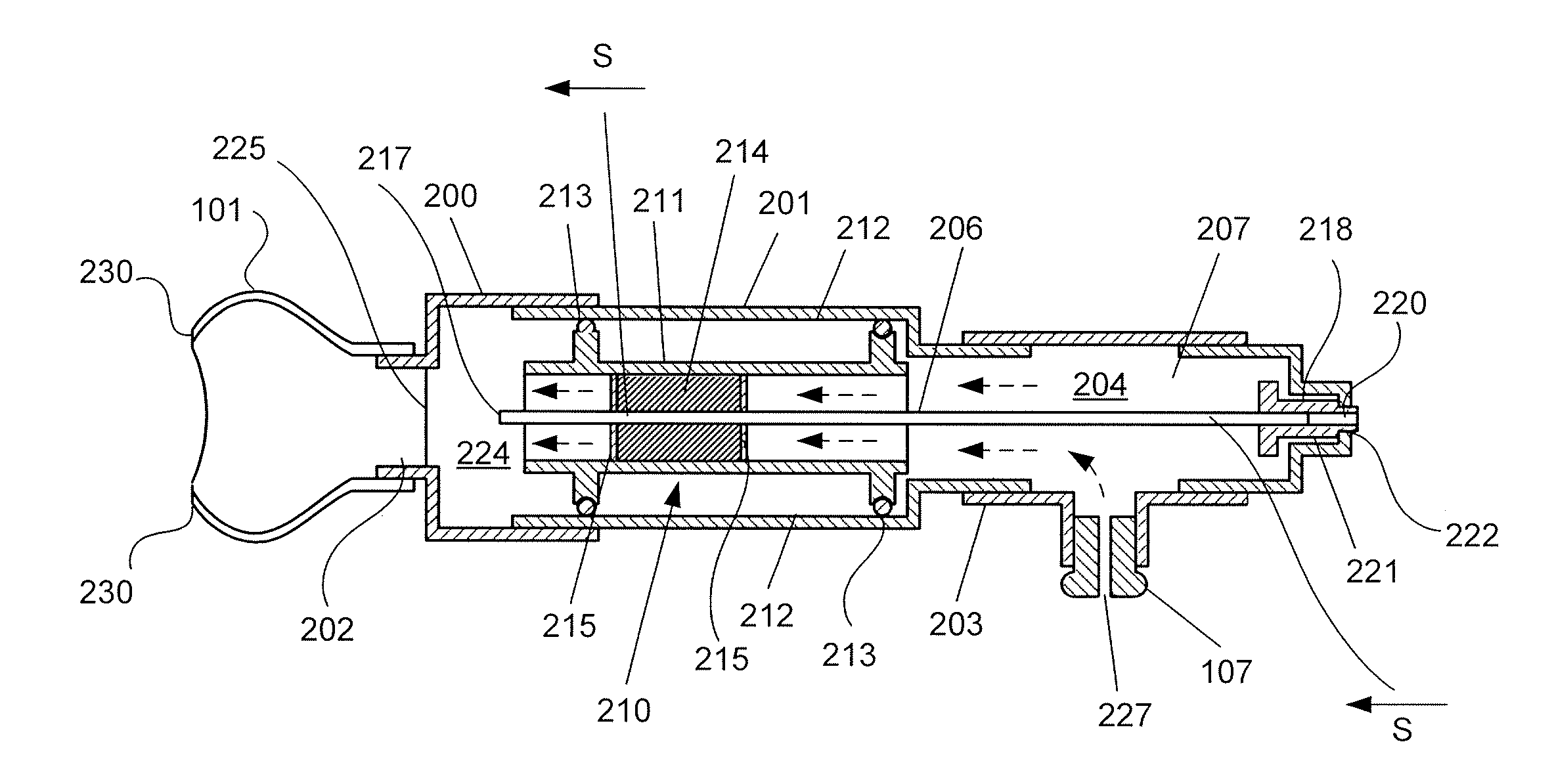
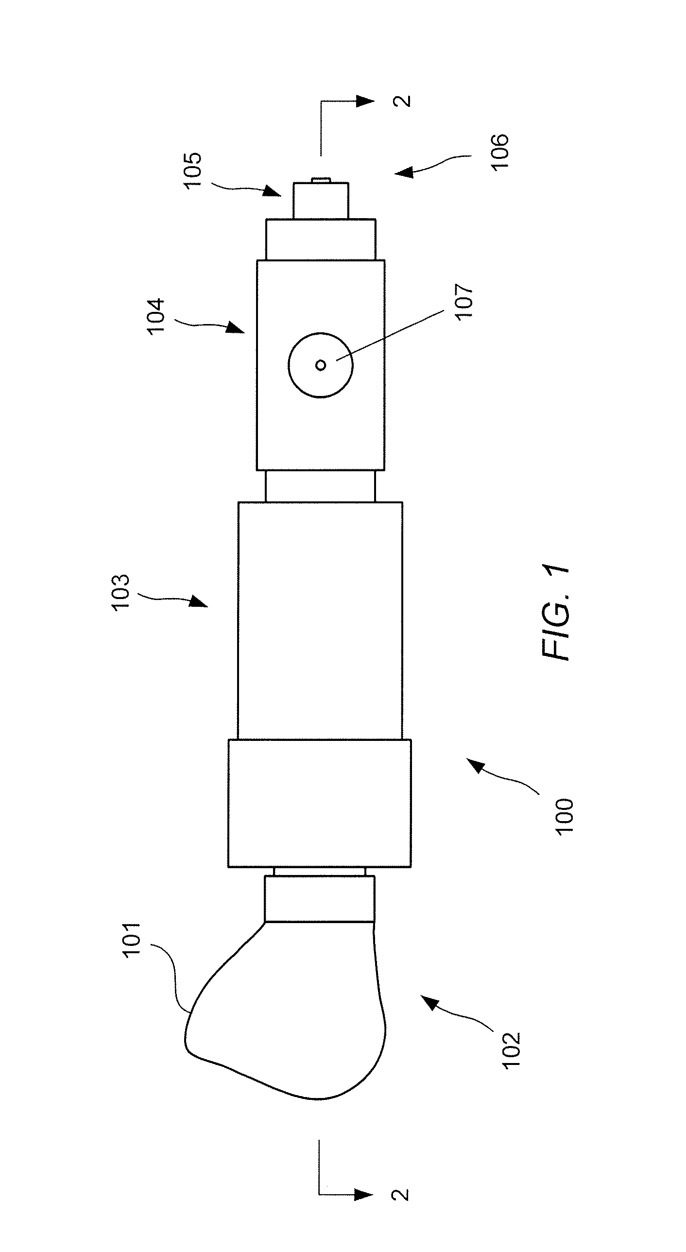
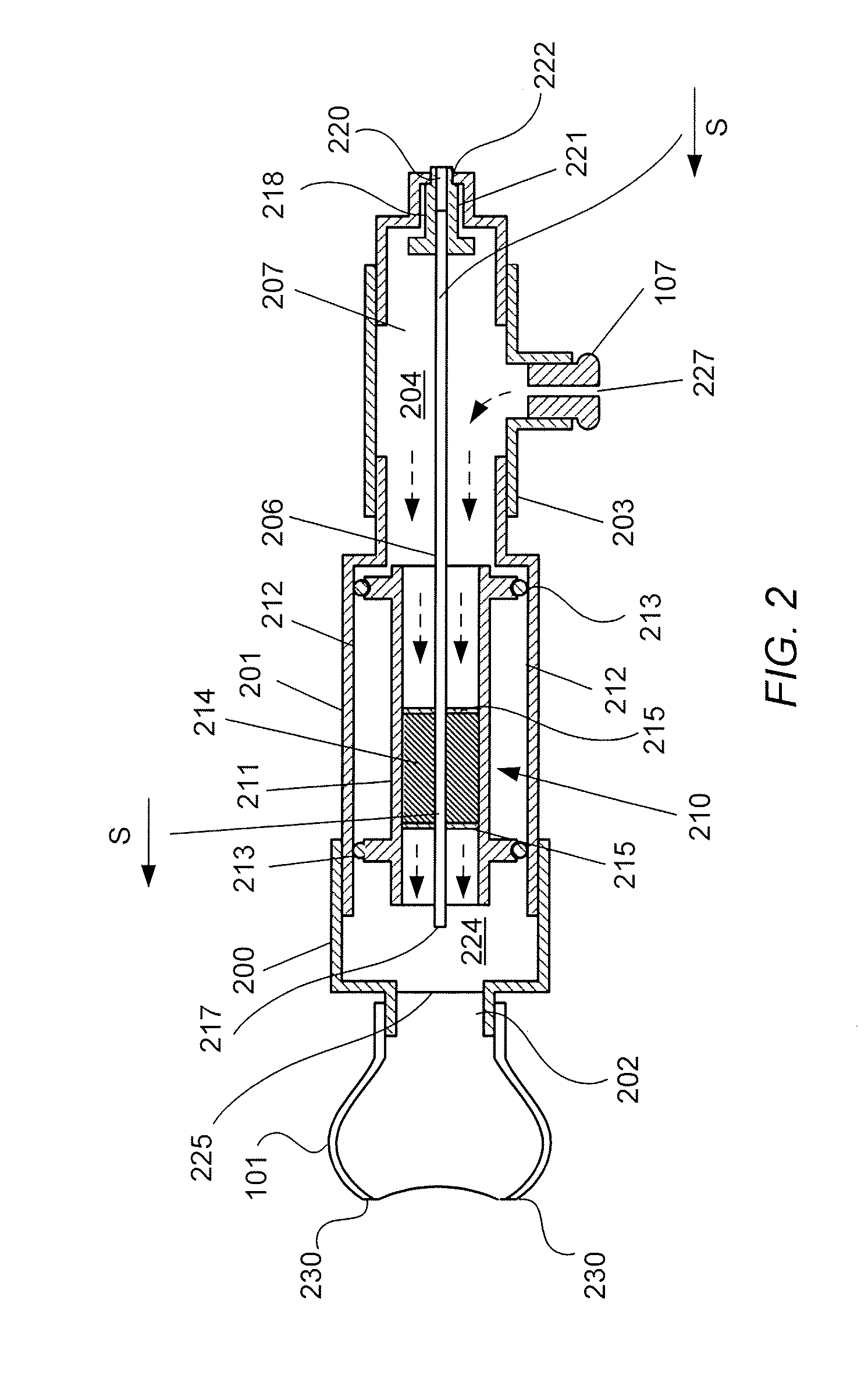
[0027]A field olfactometer 100 embodying the principles of the invention may be described with reference to FIGS. 1 through 3. As shown in FIG. 1, olfactometer 100 includes a mask 101 at an outlet end 102 of the olfactometer. Mask 101 is connected directly to one end of a filter housing 103. The end of filter housing 103 opposite the end connected to mask 101 is connected to a diluent inlet housing 104 which provides an inlet for diluent air into the olfactometer. The inlet for diluent air in this exemplary form of the invention is associated with a flow meter 107 mounted on diluent inlet housing 104. A sample inlet housing 105 is also connected to diluent inlet housing 104 at an inlet end 106 of the olfactometer opposite outlet end 102. As will be discussed below with reference to the section view shown in FIG. 2, the various housings of olfactometer 100 define a sample flow path and a diluent flow path through the device, both of which lead to a mixing chamber which is open to mas...


PUM

PropertyMeasurementUnit
diameteraaaaaaaaaa
spherical diameteraaaaaaaaaa

Abstract

A field olfactometer includes a mixing chamber connected to a mask. A sample flow path is defined through the olfactometer as is a diluent flow path. The sample flow path extends from a sample air inlet to a sample air outlet which is open to the mixing chamber. The diluent flow path extends from a diluent air inlet to a diluent air outlet which is also open to the mixing chamber. The sample flow path and diluent flow path are isolated from one another so that the sample air flowing through the sample flow path and diluent air flowing through the diluent flow path cannot mix until the two streams of air exit their respective flow path and enter the mixing chamber where the two streams mix thoroughly prior to reaching the mask. The diluent flow path includes a filter medium to remove odor-causing chemicals from ambient air drawn through the diluent flow path. A flow indicator arrangement provides a suitable indication when the flow rate at one or more points in the olfactometer reaches a predetermined value corresponding to a target dilution of diluent air to sample air. Different flow characteristics along the sample flow path as compared to the diluent flow path produces a gradually decreasing dilution ratio as a user inhales nasally at an increasing rate through the mask.

Description

CROSS-REFERENCE TO RELATED APPLICATION[0001]The Applicant claims the benefit, under 35 U.S.C. §119(e), of U.S. Provisional Patent Application Ser. No. 61 / 273,597, filed Aug. 6, 2009, entitled “Continuously Variable Field Transportable Audible Flow Alarmed Dynamic Dilution Olfactometer Device For Environmental Odor Assessment,” the entire content of which is incorporated herein by this reference.[0002]This invention was made with government support under SBIR grant No. 2007-33610-18619 awarded by the USDA. The Government has certain rights in the invention.TECHNICAL FIELD OF THE INVENTION[0003]The invention includes a low-cost field olfactometer that may be used to determine when an environmental odor is present in the ambient air in an amount which is at or above a predetermined dilution ratio. The invention also encompasses a method of olfactometry and a replaceable diluent filter cartridge assembly employed in the olfactometer and olfactometry method.BACKGROUND OF THE INVENTION[00...

Claims


Application Information

Patent Timeline
Patent Type & Authority Patents(United States)
IPC IPC(8): G01N33/497
CPCG01N33/0018
Inventor WRIGHT, DONALD
Owner DON WRIGHT & ASSOC L L C
Learn More