Bicycle rear suspension system

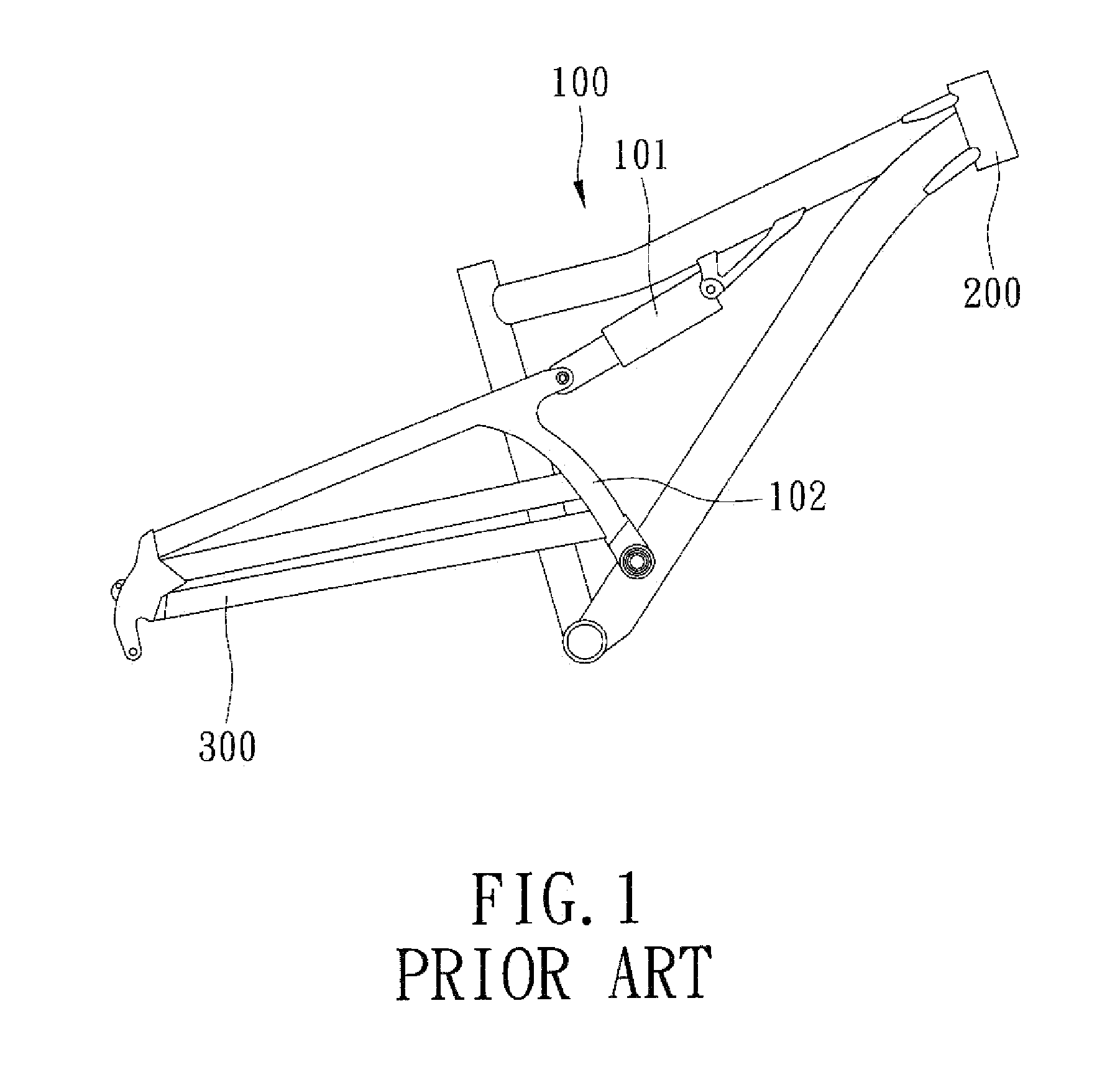
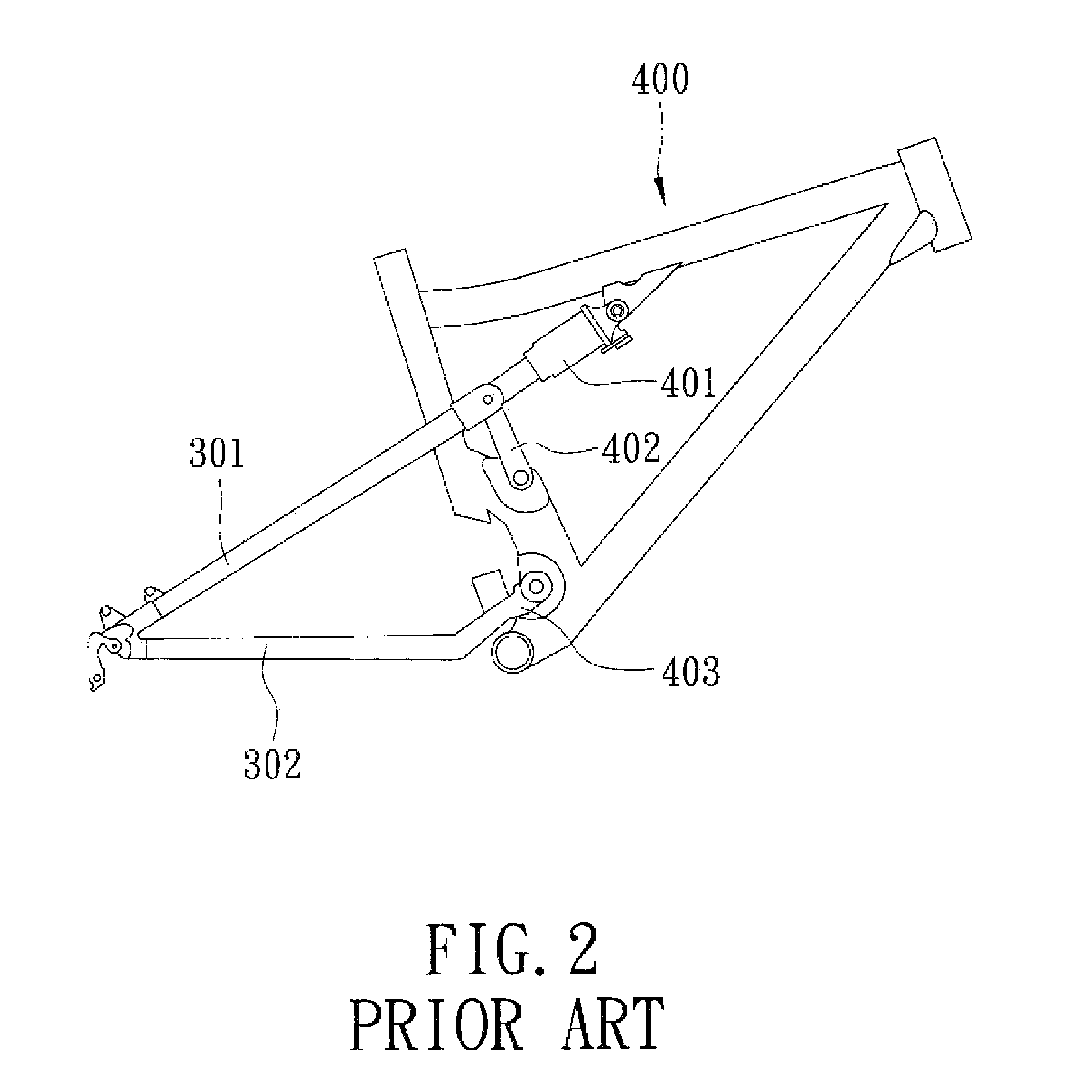
a rear suspension and bicycle technology, applied in the field of rear suspension systems, can solve the problems of lateral stiffness, affecting adversely the ride characteristics, and the lateral stiffness of the second conventional rear suspension system b>400/b> is still insufficient, and achieves the effects of cost-effectiveness, simple construction and cost-effectiveness

Inactive Publication Date: 2013-04-30
SOTTO GROUP
View PDF6 Cites 16 Cited by
  • Summary
  • Abstract
  • Description
  • Claims
  • Application Information

AI Technical Summary

Benefits of technology

[0010]The object of this invention is to provide a bicycle rear suspension system that is lightweight, cost-effective, and simple in construction.
[0011]Accordingly, a bicycle rear suspension system of this invention is adapted to be connected between front and rear triangles of a bicycle frame. The bicycle rear suspension system includes an eccentric bearing unit disposed within one of the front and rear triangles, and a connecting member connected pivotally to the other one of the front and rear triangles. The eccentric bearing unit includes an outer bearing, and an inner bearing movable within the outer bearing along an annular path. A pivot extends through the inner bearing and into the connecting member such that application of a force to the rear triangle results in movement of the inner bearing along the annular path. Since the bicycle rear suspension system is comprised of a small number of parts, it is lightweight, cost-effective, and simple in construction. Riding performance advantages of this design are seen in the stiffness of the bike which will lead the rider to have increased control of the bike in all conditions, thus allowing the recreational rider to have more fun and the competitive racer to go faster. An additional advantage is using the timing of the eccentric bearing to control shock rate, thus allowing the rider to have a smoother and more predictable ride, and the recreational rider to have a more enjoyable experience and the professional faster racing times.

Problems solved by technology

While the first conventional rear suspension system 100 is simple in construction and lightweight, it is not sufficient in lateral stiffness, thereby affecting adversely the ride characteristics.
However, the lateral stiffness of the second conventional rear suspension system 400 is still insufficient due to lack of a connecting rod between a seat stay 301 and a chain stay 302 similar to the connecting rod 102 of the first conventional rear suspension system 100.
For example, they are heavy, expensive to make, and complicated in construction.

Method used


Image

  • Bicycle rear suspension system
  • Bicycle rear suspension system
  • Bicycle rear suspension system

Examples


Embodiment Construction

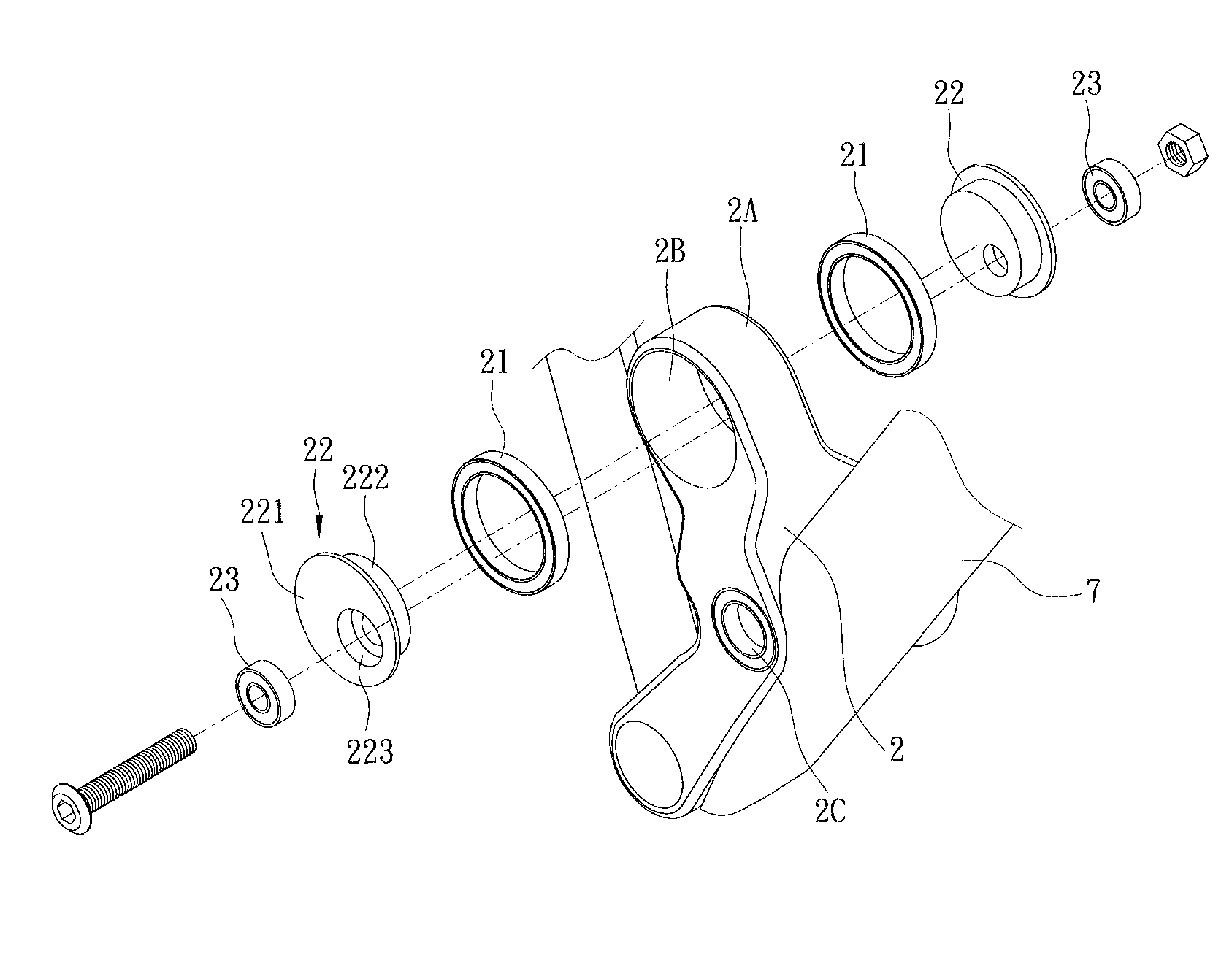
[0021]The preferred embodiment of a rear suspension system according to this invention is disposed on a bicycle that has a front triangle (F) and a rear triangle (R). Referring to FIGS. 9 and 10, the front triangle (F) includes a top tube 6, a down tube 7, and a seat tube 8, and the rear triangle (R) includes a seat stay 91 and a chain stay 92. A bottom bracket (B) is connected between lower ends of the down tube 7 and the seat tube 8. The down tube 7 has a first protrusion 1 at a middle portion thereof, and a bridge 2 adjacent to the bottom bracket (B). The seat stay 91 has a second protrusion 3.

[0022]The rear suspension system is connected between the front and rear triangles (F, R), and includes an eccentric bearing unit, a connecting member 4, and a shock absorber 5 in the form of a damping cylinder. The shock absorber 5 includes a cylinder body 51 and a piston rod 52 extending movably into the cylinder body 51.

[0023]With further reference to FIG. 11, the bridge 2 has a surround...


PUM


Abstract

A bicycle rear suspension system is connected between front and rear triangles. The suspension system includes an eccentric bearing unit disposed within one of the front and rear triangles, a connecting member connected pivotally to the other one of the front and rear triangles, and a pivot. The eccentric bearing unit includes an outer bearing, and an inner bearing movable within the outer bearing along an annular path. The pivot extends through the inner bearing of the eccentric bearing unit and into the connecting member such that, application of a force to the rear triangle results in pivoting movement of the rear triangle relative to the front triangle, and movement of the inner bearing along the annular path.

Description

CROSS-REFERENCE TO RELATED APPLICATION[0001]This application claims priority of U.S. provisional application No. 61 / 340,344, filed on Mar. 16, 2010, which is incorporated herein by reference.BACKGROUND OF THE INVENTION[0002]1. Field of the Invention[0003]This invention relates to a rear suspension system adapted to be disposed on a bicycle having a rear wheel rotatable about a pivot point of a front triangle, and more particularly to a lightweight bicycle rear suspension system that is comprised of a small number of parts and that has a relatively high lateral stiffness.[0004]2. Description of the Related Art[0005]A conventional bicycle frame typically includes a front triangle, a rear triangle, and a shock-absorbing unit connected between the front and rear triangles. The front triangle includes a head or steering tube, a top tube, a down tube, a seat tube, and a bottom bracket mounted with a crank and pedal assembly. The rear triangle includes a seat stay and a chain stay.[0006]FI...

Claims


Application Information

Patent Timeline
Patent Type & Authority Patents(United States)
IPC IPC(8): B62K25/28
CPCB62K25/20
Inventor EARLE, DAVID
Owner SOTTO GROUP
Why Eureka
Try Eureka