
System for increased floatation and stability on tension leg platform by extended buoyant pontoons

a technology of tension leg and platform, which is applied in the field of system and method of tension leg platform, can solve the problems of increased cost and extra weight of the structure, loss of production, and large topsides in both size and weight, and achieves the effects of increasing stability, expanding the stability of the tension leg platform, and increasing the buoyancy of the pontoon

Active Publication Date: 2013-04-30
TECH FRANCE SA
View PDF16 Cites 1 Cited by
  • Summary
  • Abstract
  • Description
  • Claims
  • Application Information

AI Technical Summary

Benefits of technology

This configuration increases the TLP's resistance to adverse movements by 10-35% compared to traditional designs, providing enhanced stability during head and quartering storms, and reduces the risk of capsize even if one tendon is lost.

Problems solved by technology

These reservoirs usually require large drilling rig and drilling variable payload which result in very large topsides in both size and weight.
Thus, the cost and extra weight of the structure can increase.
In 2005, two large hurricanes, Katrina and Rita, occurring within one month of each other in the Gulf of Mexico, United States, caused a significant loss of life, loss of platforms, and loss of production.
The design criteria used at that time for offshore platforms had not predicted such stress loading on many of the existing platforms.
The hurricanes destroyed over one hundred offshore platforms and damaged many others.
In at least one instance of a floating TLP, the tendons ripped loose from the anchors or simply broke on one or more corners, leaving the remaining tendons taught, and causing the platform to overturn and capsize.
However, it is believed that the design of such radial wings form a discontinuous transition and are at a non-parallel angle with the pontoons and can create a failure mode between the radial wing and the pontoon assembly or adjacent column.

Method used


Image

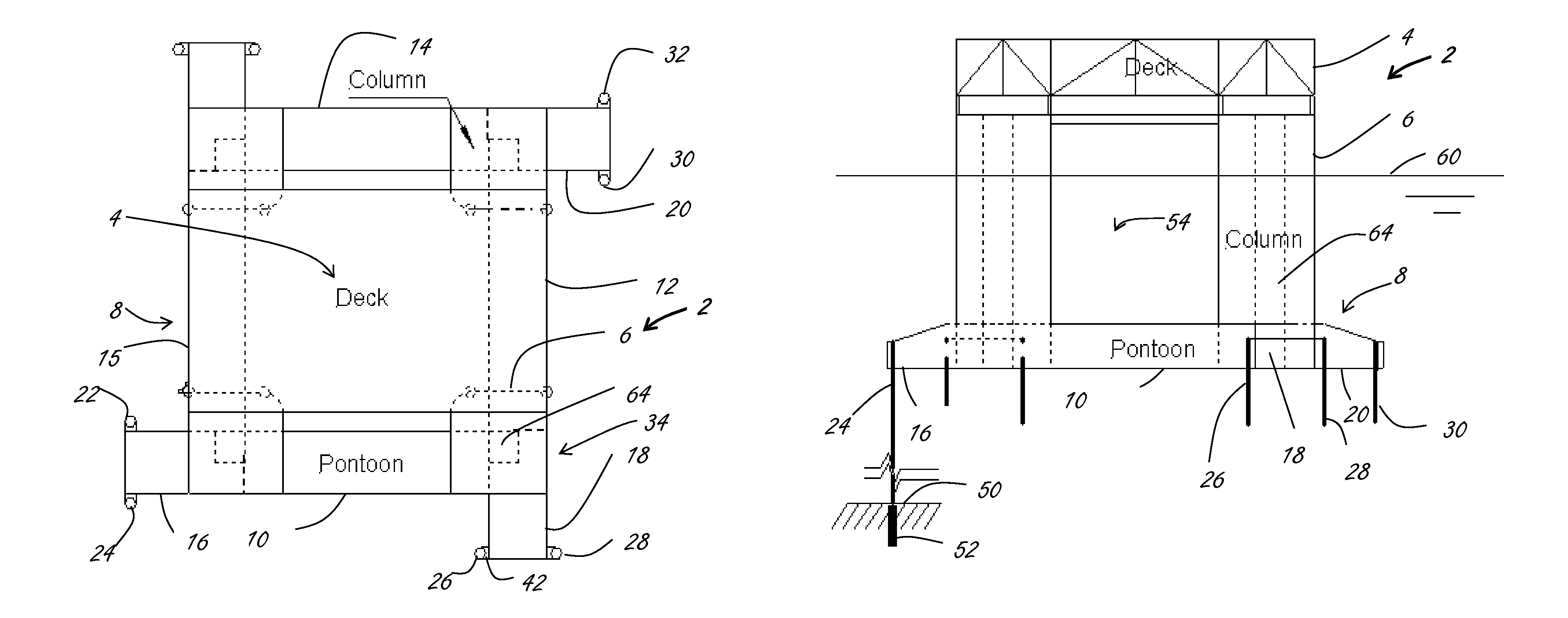
  • System for increased floatation and stability on tension leg platform by extended buoyant pontoons
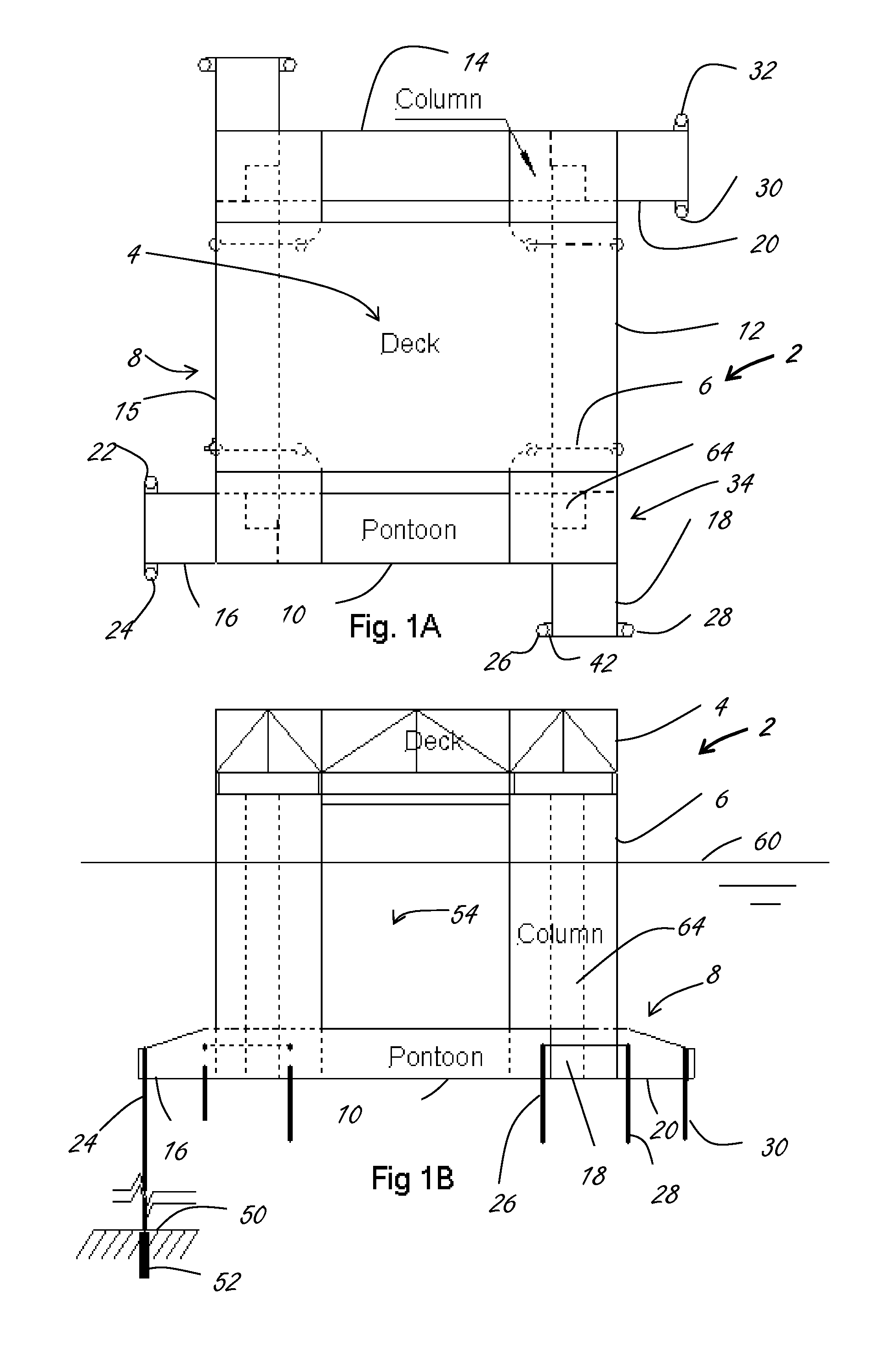
  • System for increased floatation and stability on tension leg platform by extended buoyant pontoons
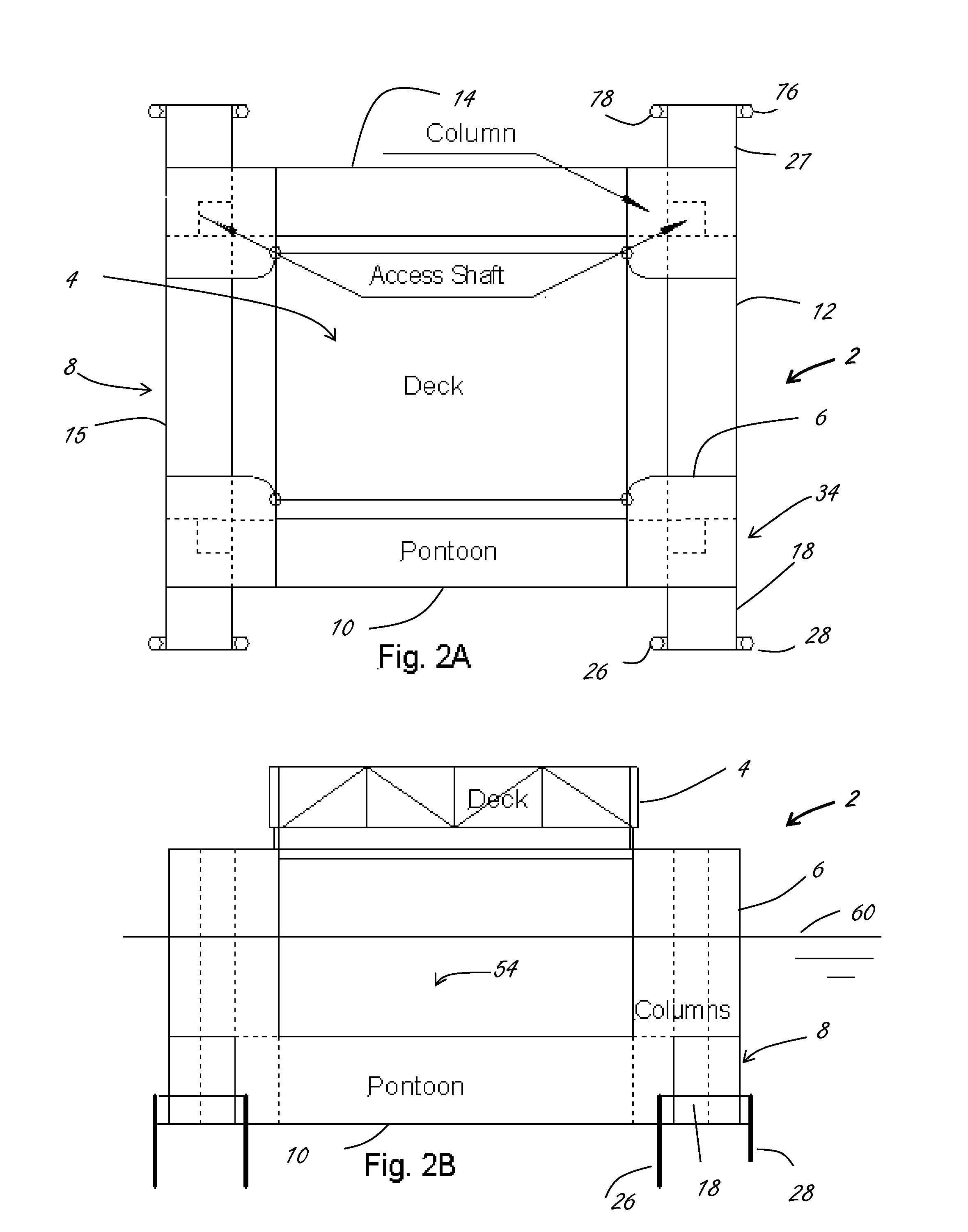
  • System for increased floatation and stability on tension leg platform by extended buoyant pontoons

Examples


Embodiment Construction

[0025]The Figures described above and the written description of specific structures and functions below are not presented to limit the scope of what Applicant has invented or the scope of the appended claims. Rather, the Figures and written description are provided to teach any person skilled in the art how to make and use the inventions for which patent protection is sought. Those skilled in the art will appreciate that not all features of a commercial embodiment of the inventions are described or shown for the sake of clarity and understanding. Persons of skill in this art will also appreciate that the development of an actual commercial embodiment incorporating aspects of the present inventions will require numerous implementation-specific decisions to achieve the developer's ultimate goal for the commercial embodiment. Such implementation-specific decisions may include, and likely are not limited to, compliance with system-related, business-related, government-related and other...


PUM


Abstract

The disclosure provides a tension leg platform (“TLP”) with a plurality of buoyant pontoons suitable for highly disturbed seas that can expand the stability of the tension leg platform by extending at least one buoyant pontoon beyond an intersection of two pontoons. In at least one embodiment, the location of the column can be decoupled from the customary end of the pontoon. The tendons can be located at the ends of the pontoons extending beyond the intersection. In some embodiments, such as four-column TLPs, the pontoons can be extended orthogonally relative to an adjacent pontoon. The extending pontoon increases a buoyancy of the pontoon, increases a pitch stability of the TLP, and increases quayside stability. The extended pontoon can be structurally intersected with the adjacent pontoon to strengthen the extended pontoon and reduce the failure mode of such structure.

Description

CROSS REFERENCE TO RELATED APPLICATIONS[0001]Not applicable.STATEMENT REGARDING FEDERALLY SPONSORED RESEARCH OR DEVELOPMENT[0002]Not applicable.REFERENCE TO APPENDIX[0003]Not applicable.BACKGROUND OF THE INVENTION[0004]1. Field of the Invention[0005]The disclosure relates generally to a system and method for offshore floating structures for use in the oilfield and related industries for exploration and extraction of minerals and resources from below surface waters. More specifically, the disclosure relates to a system and method for tension leg platforms for offshore exploration and production.[0006]2. Description of the Related Art[0007]With the significantly increasing demand on the oil and gas supply, offshore exploration and production from reservoirs has become vital to such supply. These reservoirs usually require large drilling rig and drilling variable payload which result in very large topsides in both size and weight. Spars and Tension Leg Platforms (“TLPs”) are the only t...

Claims


Application Information

Patent Timeline
Patent Type & Authority Patents(United States)
IPC IPC(8): B63B35/44
CPCB63B43/14B63B35/4413B63B21/502B63B1/107B63B2039/067B63B2001/128
Inventor XU, QILUO, MICHAEL Y. H.BARRAS, STEVENO'SULLIVAN, JAMES
Owner TECH FRANCE SA
Learn More