
Wireless charging system and method

a charging system and wireless technology, applied in battery data exchange, transportation and packaging, sustainable buildings, etc., can solve the problems of different charging efficiency of wireless charging system and deterioration of wireless communication performance, and achieve the effect of ensuring the stability of mobile terminals, minimizing performance influence, and no influence on wireless communication performan

Active Publication Date: 2013-04-30
SAMSUNG ELECTRONICS CO LTD
View PDF7 Cites 32 Cited by
  • Summary
  • Abstract
  • Description
  • Claims
  • Application Information

AI Technical Summary

Benefits of technology

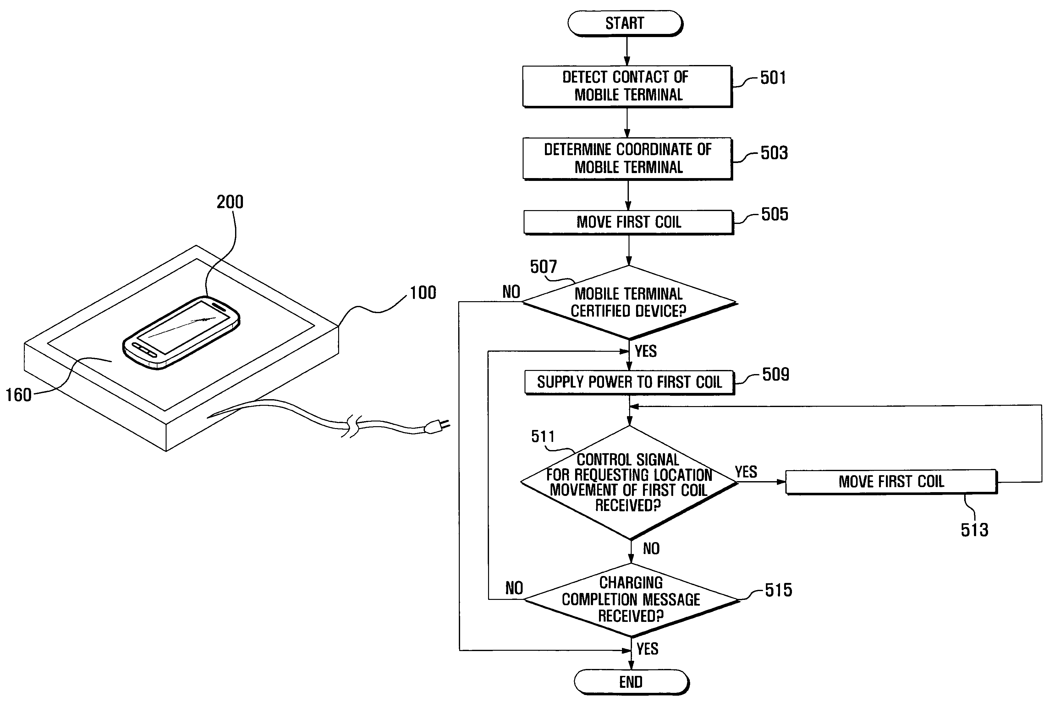
[0005]To address the above-discussed deficiencies of the prior art, it is a primary object to provide a wireless charging system and method that secure stability of a mobile terminal by minimizing an influence on performance and a lifetime of parts of the mobile terminal, and that have no influence on wireless communication performance, and that sustain optimum charging efficiency regardless of a location of the mobile terminal.

Problems solved by technology

However, such a wireless charging system has different charging efficiency according to a location relationship of the first coil and the second coil.
However, such a conventional method has a problem that wireless communication performance is deteriorated due to an influence of a magnetic field generating by the first coil and because the magnetic field is induced in a high and wide area, performance and a lifetime of parts of a mobile terminal may be influenced.

Method used


Image

  • Wireless charging system and method
  • Wireless charging system and method
  • Wireless charging system and method

Examples


Embodiment Construction

[0017]FIGS. 1 through 6, discussed below, and the various embodiments used to describe the principles of the present disclosure in this patent document are by way of illustration only and should not be construed in any way to limit the scope of the disclosure. Those skilled in the art will understand that the principles of the present disclosure may be implemented in any suitably arranged portable terminal.

[0018]While the present invention may be embodied in many different forms, specific embodiments of the present invention are shown in drawings and are described herein in detail, with the understanding that the present disclosure is to be considered as an exemplification of the principles of the invention and is not intended to limit the invention to the specific embodiments illustrated.

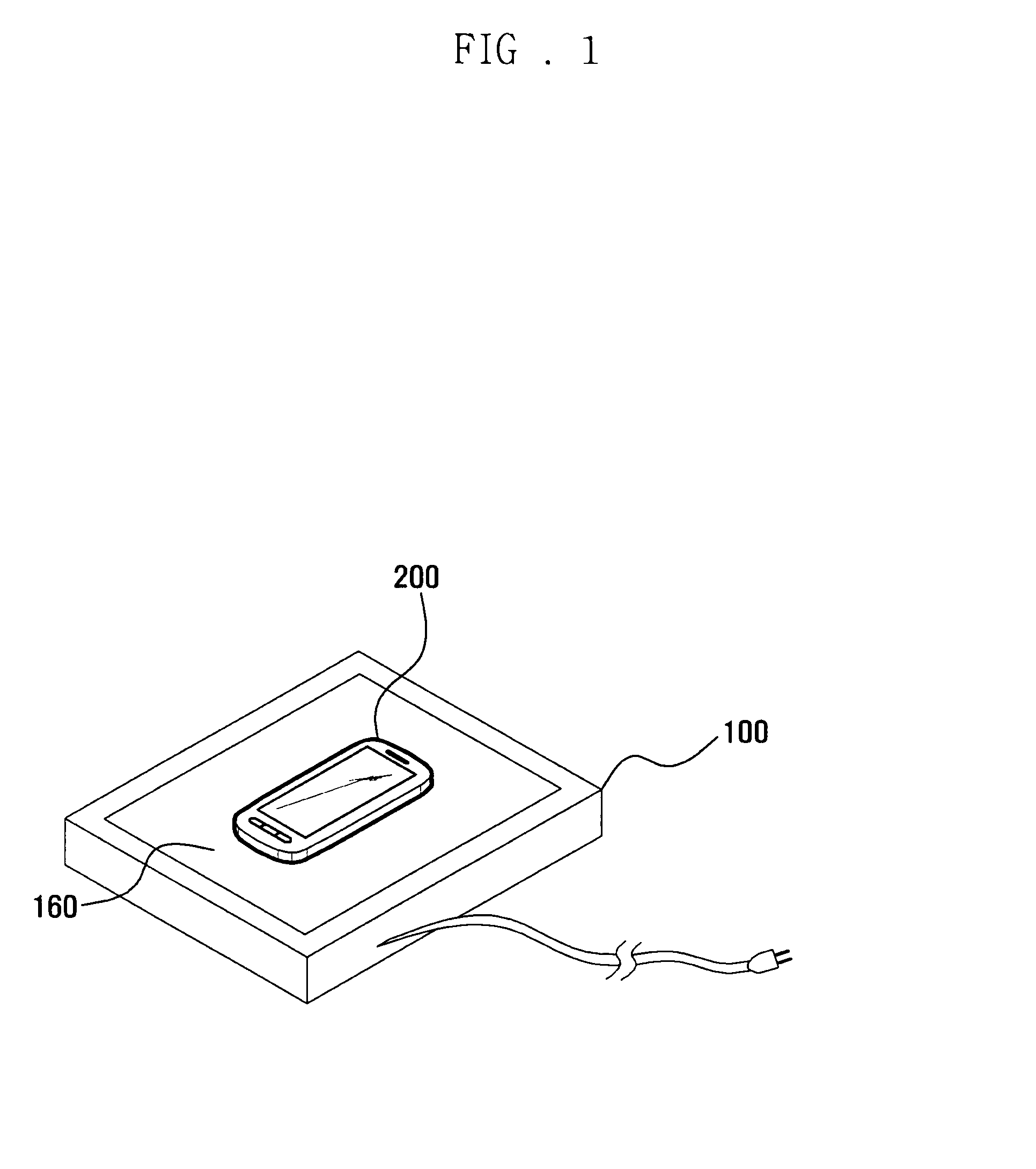
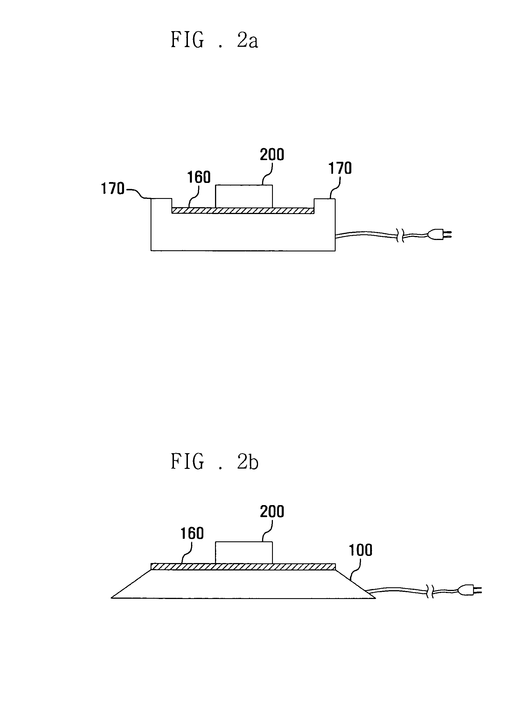
[0019]In the following description, a “charging pad” is a charging device for wireless charging of a mobile terminal. “Charging efficiency” indicates a degree in which electric power supplied for c...


PUM


Abstract

A wireless charging system can optimize charging efficiency regardless of a location of a mobile terminal. The wireless charging system wirelessly charges a mobile terminal using electromagnetic induction between a first coil included in a charging pad and a second coil included in the mobile terminal. The charging pad can detect a location of the mobile terminal on the charging pad. The charging pad can move the first coil to correspond to the detected location of the mobile terminal; and supply power to the first coil and charging a battery.

Description

CROSS-REFERENCE TO RELATED APPLICATION(S) AND CLAIM OF PRIORITY[0001]The present application is related to and claims priority to an application entitled “WIRELESS CHARGING SYSTEM AND METHOD” filed in the Korean Intellectual Property Office on Dec. 24, 2008 and assigned Serial No. 10-2008-0133078, the contents of which are incorporated herein by reference.TECHNICAL FIELD OF THE INVENTION[0002]The present invention relates to a wireless charging system and method, and more particularly, to a wireless charging system and method for a mobile terminal that can optimize charging efficiency regardless of a location of a mobile terminal.BACKGROUND OF THE INVENTION[0003]Nowadays, mobile terminals provide various functions such as a wireless Internet function, electronic note function, multimedia photographing and reproducing function, and game player function, digital broadcasting function in addition to a basic communication function. Such a mobile terminal generally uses a battery for por...

Claims


Application Information

Patent Timeline
Patent Type & Authority Patents(United States)
IPC IPC(8): H02J7/00
CPCH02J7/025H02J7/0052Y02B40/90H02J7/0042H02J50/10H02J50/90H02J50/80H02J7/00045H02J7/00
Inventor LEE, CHANG KIJUNG, WON BAE
Owner SAMSUNG ELECTRONICS CO LTD
Learn More