
Line printing device and method performing color conversion and halftoning on image data subjected to correction based on correction vectors associated with a pixel row and reference color

a printing device and color conversion technology, applied in the field of printing devices and printing methods, can solve the problems of mixing-color unevenness, streak-like density unevenness in printed images, and the inability to achieve uniformity, so as to reduce the unevenness of printed images

Active Publication Date: 2013-04-30
SEIKO EPSON CORP
View PDF5 Cites 0 Cited by
  • Summary
  • Abstract
  • Description
  • Claims
  • Application Information

AI Technical Summary

Benefits of technology

[0010]An object of the present invention is to reduce unevenness in printed images composed of multiple superimposed colors.

Problems solved by technology

In some instances, streak-like density unevenness may occur in printed images.
It is thought that such density unevenness is caused by failure of the multitude of dot rows making up a printed image from being formed in ideal fashion due to the effects of manufacturing errors of the heads, so that individual dot rows are darker or lighter depending on dot size, or the dot rows are formed out of alignment.
However, there are instances in which, notwithstanding successful respective correction of density unevenness of images of the colors of the same color space as the ink colors, unevenness (mixed-color unevenness) arises in the printed image composed of these multiple superimposed colors.

Method used


Image

  • Line printing device and method performing color conversion and halftoning on image data subjected to correction based on correction vectors associated with a pixel row and reference color
  • Line printing device and method performing color conversion and halftoning on image data subjected to correction based on correction vectors associated with a pixel row and reference color
  • Line printing device and method performing color conversion and halftoning on image data subjected to correction based on correction vectors associated with a pixel row and reference color

Examples


first reference example

Normal Process of Printer Driver

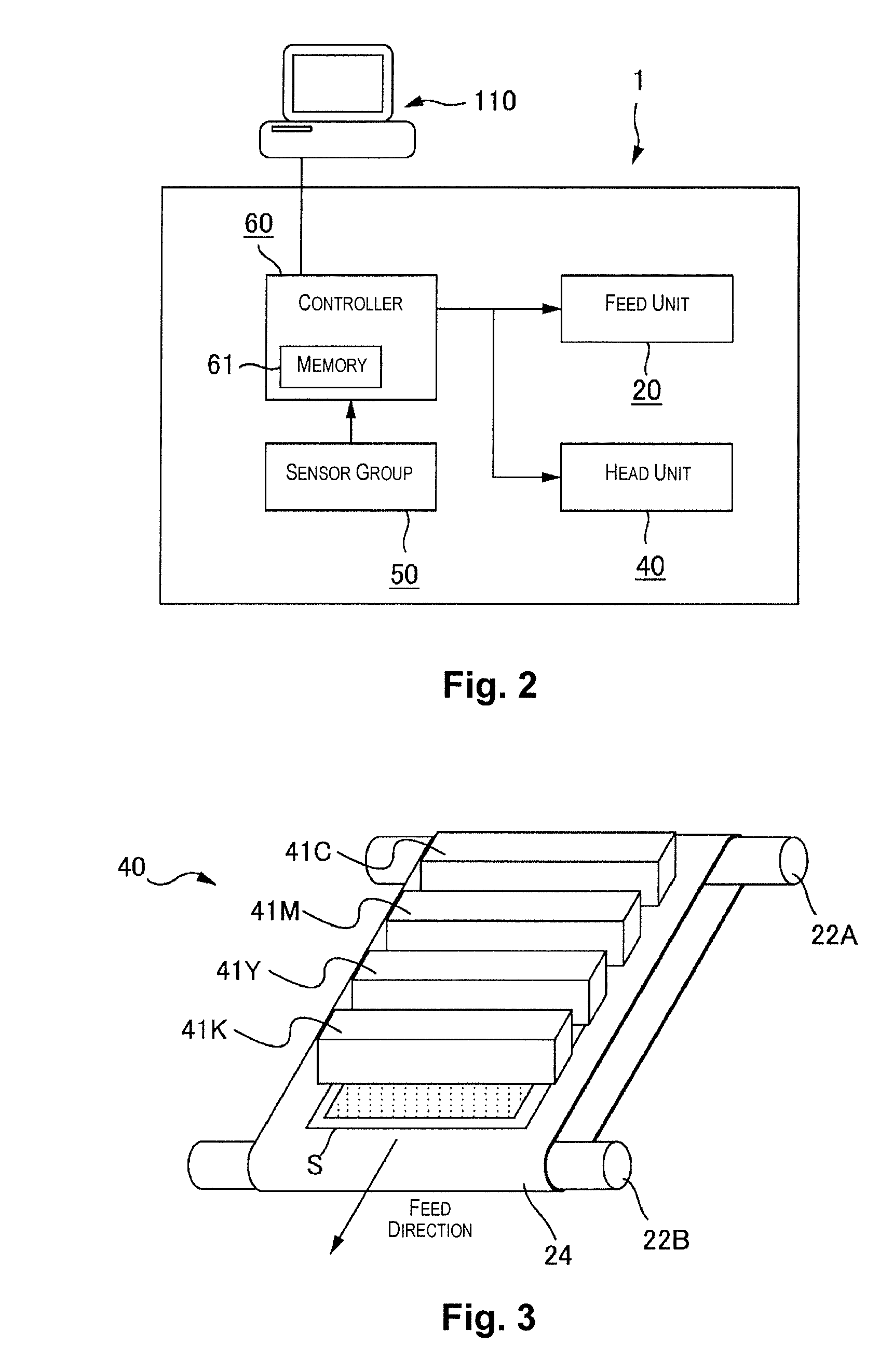
[0071]A printer driver is installed on the computer 110 (FIG. 2). The computer 110 on which the printer driver has been installed functions as a print control device for controlling the printer 1. The printer driver receives image data (input image data) from an application program, converts this to print data of a format that can be rendered by the printer 1, and outputs the print data to the printer. During conversion of input image data to print data, the printer driver carries out processes such as a color conversion process and a halftoning process.

[0072]FIG. 6A is an illustration of a process of a printer driver in a first reference example. The first reference example is a process that does not involve correcting density unevenness.

[0073]Prior to the color conversion process, the image data is 256-tone RGB color space image data. If necessary, prior to the color conversion process, the printer driver carries out a resolution conversion process ...

second reference example

Single-Color Unevenness Correction Process

[0078]Where printing is carried out according to the normal process of the first reference example, in some instances streak-like density unevenness may occur in the printed image. This density unevenness is thought to be caused by failure of the multitude of dot rows that make up the printed image to be formed in ideal fashion due to the effects of manufacturing errors of the heads, so that individual dot rows are darker or lighter depending on dot size, or the dot rows are formed out of alignment.

[0079]Because the printed image is composed of superimposed images of the same color space as the ink colors, it is thought that if density unevenness of the individual colors (single-color unevenness) of the same color space as the ink colors is respectively suppressed, density unevenness in the printed image as a whole may be suppressed as well. According to this second reference example, density unevenness is respectively detected on an individ...

embodiment

Mixed Color Unevenness Correction Process Method of Acquiring Mixed-Color Unevenness Correction Values

[0120]First, the method of acquiring mixed-color unevenness correction values is described. The process of acquiring mixed-color unevenness correction values is carried out during the inspection process at the factory where the printer 1 is manufactured (however, acquisition of mixed-color unevenness correction values may also be carried out by the user who has purchased the printer 1).

[0121]FIG. 16 is a flow chart of the mixed-color unevenness correction value acquisition process. Circumstances up to the point that the printer 1 acquires mixed-color unevenness correction values are comparable to those in FIGS. 7A to 7C discussed previously.

[0122]Initially, the inspector connects the printer 1 being inspected to a computer 110 at the factory (see FIG. 7A). A scanner 150 is also connected to this computer 110. A printer driver, a scanner driver, and a correction value acquisition pro...


PUM


Abstract

For each of a plurality of reference colors located at prescribed coordinates in a first color space (e.g., the RGB color space), there are associated, on an individual pixel row basis, correction vectors indicating correction amounts in the first color space. For each pixel datum of image data of first tone values (e.g., 256 tone values) of the first color space prior to a color conversion process, a correction process is carried out on the basis of the correction vector that has been associated with the pixel row to which a given pixel belongs, the correction vector also being associated with the reference color of a location surrounding the coordinates that indicate the pixel data in the first color space. The color conversion process and the halftoning process are carried out on image data composed of the pixel data that has been subjected to the correction process.

Description

CROSS-REFERENCE TO RELATED APPLICATIONS[0001]This application claims priority to Japanese Patent Application No. 2010-068669 filed on Mar. 24, 2010. The entire disclosure of Japanese Patent Application No. 2010-068669 is hereby incorporated herein by reference.BACKGROUND[0002]1. Technical Field[0003]The present invention relates to a printing device and to a printing method.[0004]2. Related Art[0005]Printing devices that employ an inkjet system whereby printing onto a medium (such as paper, fabric, or OHP transparency film) is carried out by expelling ink from a head on which a multitude of nozzles are arrayed are known in the art. Known printing devices of this kind include line printers, in which the medium is fed with respect to a stationary head; and serial printers, in which an operation of moving the head while expelling ink and an operation of feeding the medium are repeated in alternating fashion. Known systems for expelling ink from the head include piezoelectric systems em...

Claims


Application Information

Patent Timeline
Patent Type & Authority Patents(United States)
IPC IPC(8): H04N1/58H04N1/60
CPCB41J2/2146H04N1/6038H04N1/6041
Inventor MIYAMOTO, TORU
Owner SEIKO EPSON CORP
Learn More