
Ribbon microphone with rounded magnet motor assembly, backwave chamber, and phantom powered JFET circuit

a magnet motor and microphone technology, applied in the direction of transducer details, mouthpiece/microphone attachments, electrical transducers, etc., can solve the problems of reducing affecting the performance of the microphone, and affecting the output signal level of most ribbon microphones, so as to improve or flatter the frequency response, improve the frequency response, and reduce the acoustic pressure

Active Publication Date: 2013-04-30
CLOUD MICROPHONES LLC
View PDF1 Cites 7 Cited by
  • Summary
  • Abstract
  • Description
  • Claims
  • Application Information

AI Technical Summary

Benefits of technology

The invention provides an improved backwave chamber for a ribbon microphone that reduces acoustic pressure, sound reflections, phase cancellation, and doubling effects to achieve flatter frequency responses. The chamber consists of a primary chamber and a secondary chamber that are connected through an opening, which helps to reduce these negative effects.

Problems solved by technology

However, the classic ribbon microphone architecture was susceptible to significant disadvantages.
First, a typical ribbon microphone contained a fragile ultra-thin ribbon, typically made of corrugated aluminum, which could break easily if the ribbon microphone casing was subject to a gust of air through its microphone windscreen.
Second, most ribbon microphones could not produce as high output signal level as condenser or dynamic microphones.
The lack of high output signal level for ribbon microphones usually required careful pre-amplification matching and tuning, which was cumbersome and contributed to reduced ruggedness and reliability compared to condenser and dynamic microphones.
As Compact Discs and solid-state non-volatile memory (e.g. NAND flash memory) became recording media of choice for highly digitized recording and broadcasting equipment, the high-frequency exaggeration and distortion provided by condenser microphones were no longer desirable.

Method used


Image

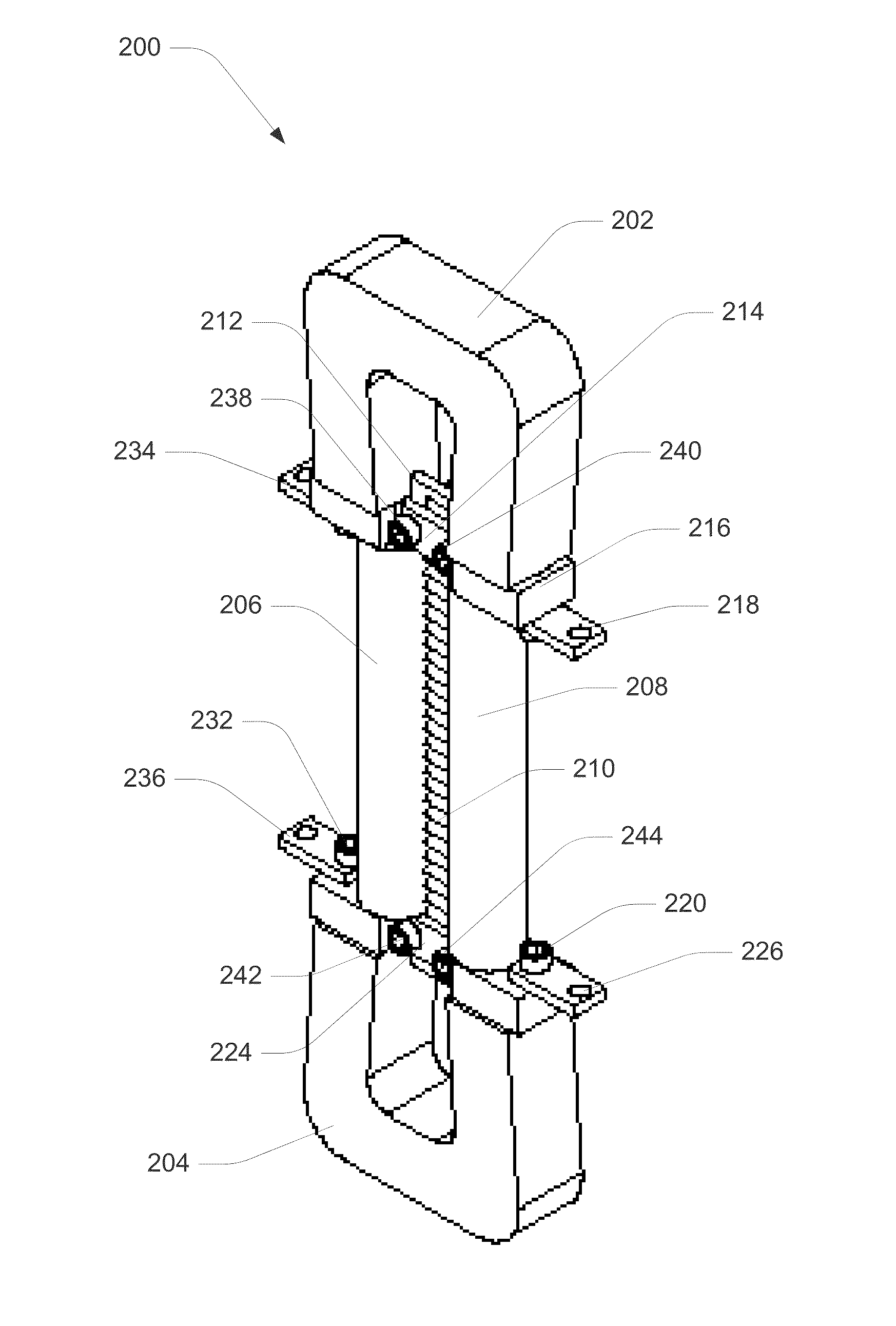
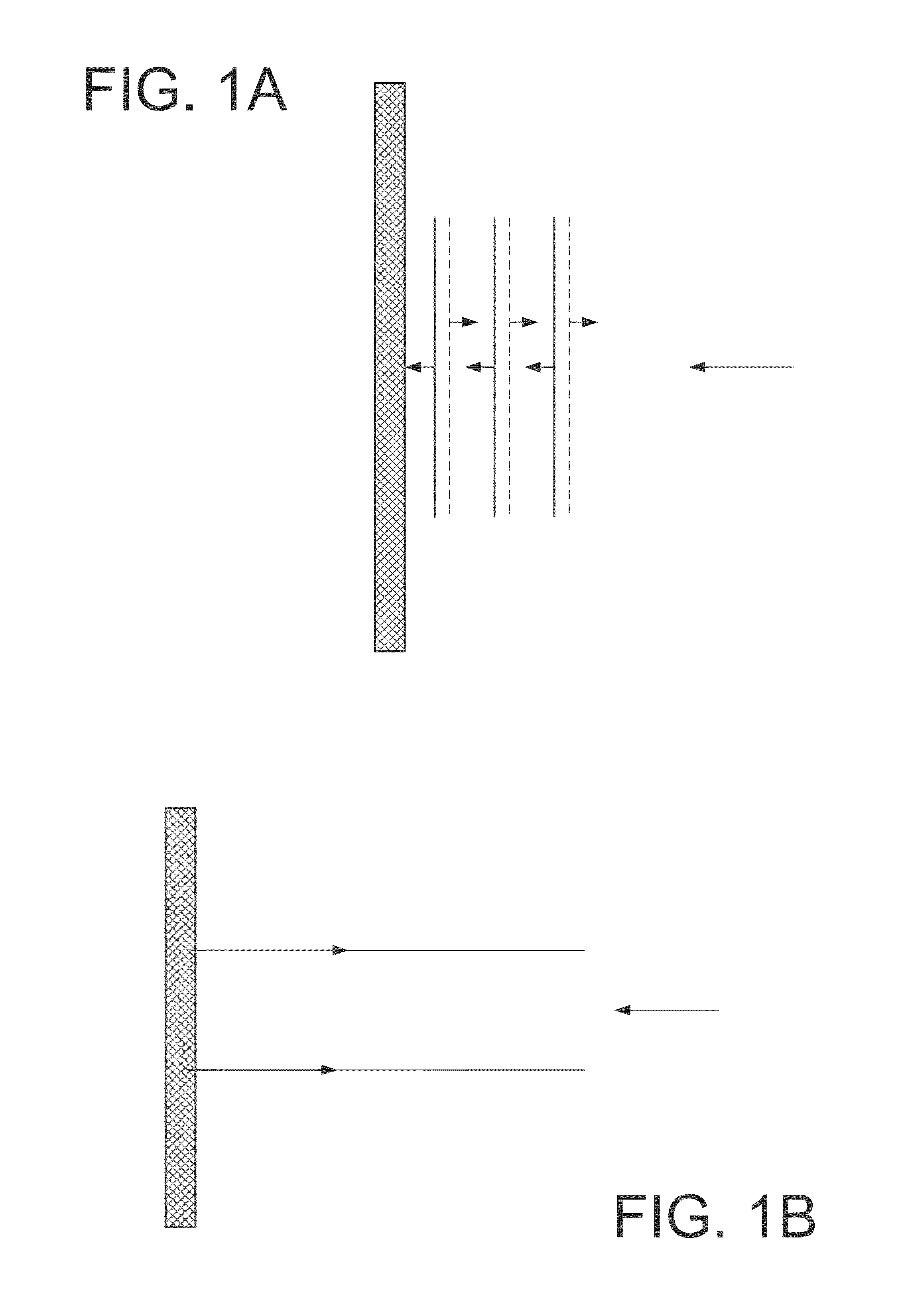
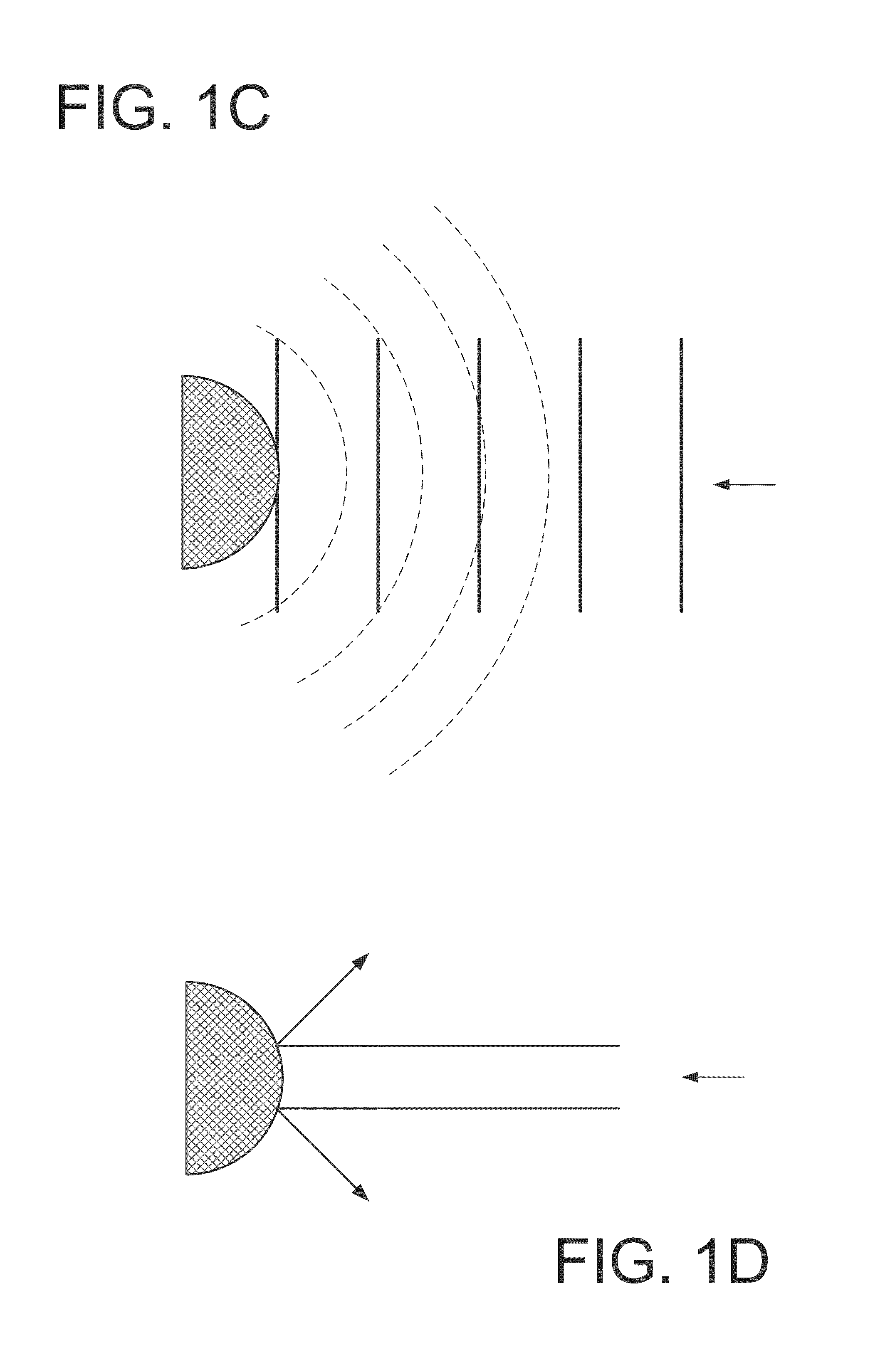
  • Ribbon microphone with rounded magnet motor assembly, backwave chamber, and phantom powered JFET circuit
  • Ribbon microphone with rounded magnet motor assembly, backwave chamber, and phantom powered JFET circuit
  • Ribbon microphone with rounded magnet motor assembly, backwave chamber, and phantom powered JFET circuit

Examples


Embodiment Construction

[0042]Specific embodiments of the invention will now be described in detail with reference to the accompanying figures. Like elements in the various figures are denoted by like reference numerals for consistency.

[0043]In the following detailed description of embodiments of the invention, numerous specific details are set forth in order to provide a more thorough understanding of the invention. However, it will be apparent to one of ordinary skill in the art that the invention may be practiced without these specific details. In other instances, well-known features have not been described in detail to avoid unnecessarily complicating the description.

[0044]The detailed description is presented largely in terms of description of shapes, configurations, and / or other symbolic representations that directly or indirectly resemble a ribbon microphone with rounded magnet motor assembly, a backwave chamber, and / or a phantom-powered JFET Circuit. These process descriptions and representations a...


PUM


Abstract

A novel ribbon microphone incorporates rounded-edge magnet motor assembly, a backwave chamber, and a phantom-powered JFET circuit. In one embodiment of the invention, one or more novel rounded-edge magnets may be placed close to a ribbon of the ribbon microphone, wherein the one or more novel rounded-edge magnets reduce or minimize reflected sound wave interferences with the vibration of the ribbon during an operation of the ribbon microphone. Furthermore, in one embodiment of the invention, a novel backwave chamber operatively connected to a backside of the ribbon can minimize acoustic pressure, anomalies in frequency responses, and undesirable phase cancellation and doubling effects. Moreover, in one embodiment of the invention, a novel phantom-powered JFET preamplifier gain circuit can minimize undesirable sound distortions and reduce the cost of producing a conventional preamplifier gain circuit.

Description

BACKGROUND OF THE INVENTION[0001]In the first half of the 20th century, ribbon microphones once dominated commercial broadcasting and recording industries as a preferred high-end microphone technology. First developed by Dr. Harry F. Olson of RCA corporation in the late 1920's, Ribbon microphones widely commercialized in the 1930's exhibited superior frequency responses and higher-fidelity output signals compared to many condenser microphones of the time.[0002]A ribbon microphone typically uses a thin piece of metal immersed in magnetic field generated by surrounding magnets. The thin piece of metal is generally called a “ribbon” and is often corrugated to achieve wider frequency response and fidelity. Ribbon microphones became vastly popular and became a primary broadcasting and recording microphone until mid-1960's.[0003]However, the classic ribbon microphone architecture was susceptible to significant disadvantages. First, a typical ribbon microphone contained a fragile ultra-thi...

Claims


Application Information

Patent Timeline
IPC IPC(8): H04R9/06
CPCH04R9/025H04R3/00H04R1/08H04R1/222H04R1/2876H04R9/048H04R1/083
Inventor CLOUD, RODGERSANK, STEPHEN
Owner CLOUD MICROPHONES LLC
Learn More