Near-field magnetic communication antenna

Active Publication Date: 2016-12-29
NEAR FIELD MAGNETICS
View PDF1 Cites 7 Cited by
  • Summary
  • Abstract
  • Description
  • Claims
  • Application Information

AI Technical Summary

Benefits of technology

[0012]The prior art systems mentioned above fail to reduce coupling between collocated transmit and receive antennas while also maximizing signal range. Antennas of the present invention solve this problem by eliminating the coupling of the transmit signal into the receiver when the transmit coil and the receive coil are collocated on parallel planes or on a single plane. By placing one or more receive coils inside the closed geometry of the transmit coil, placing one or more receive coils outside of the transmit coil, and connecting all of the receive coils in series, the transmit signal is eliminated or sufficiently reduced from

Problems solved by technology

The prior art systems mentioned above fail to reduce coupling between col

Method used


Image

  • Near-field magnetic communication antenna
  • Near-field magnetic communication antenna
  • Near-field magnetic communication antenna

Examples


Embodiment Construction

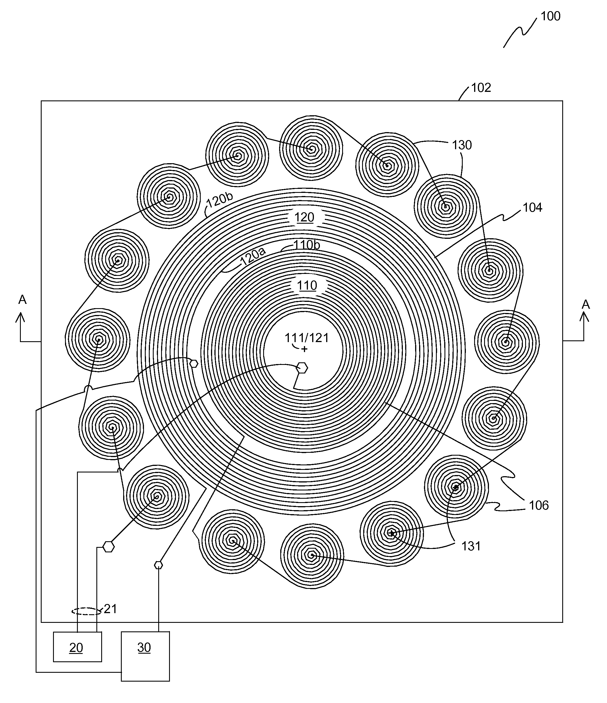
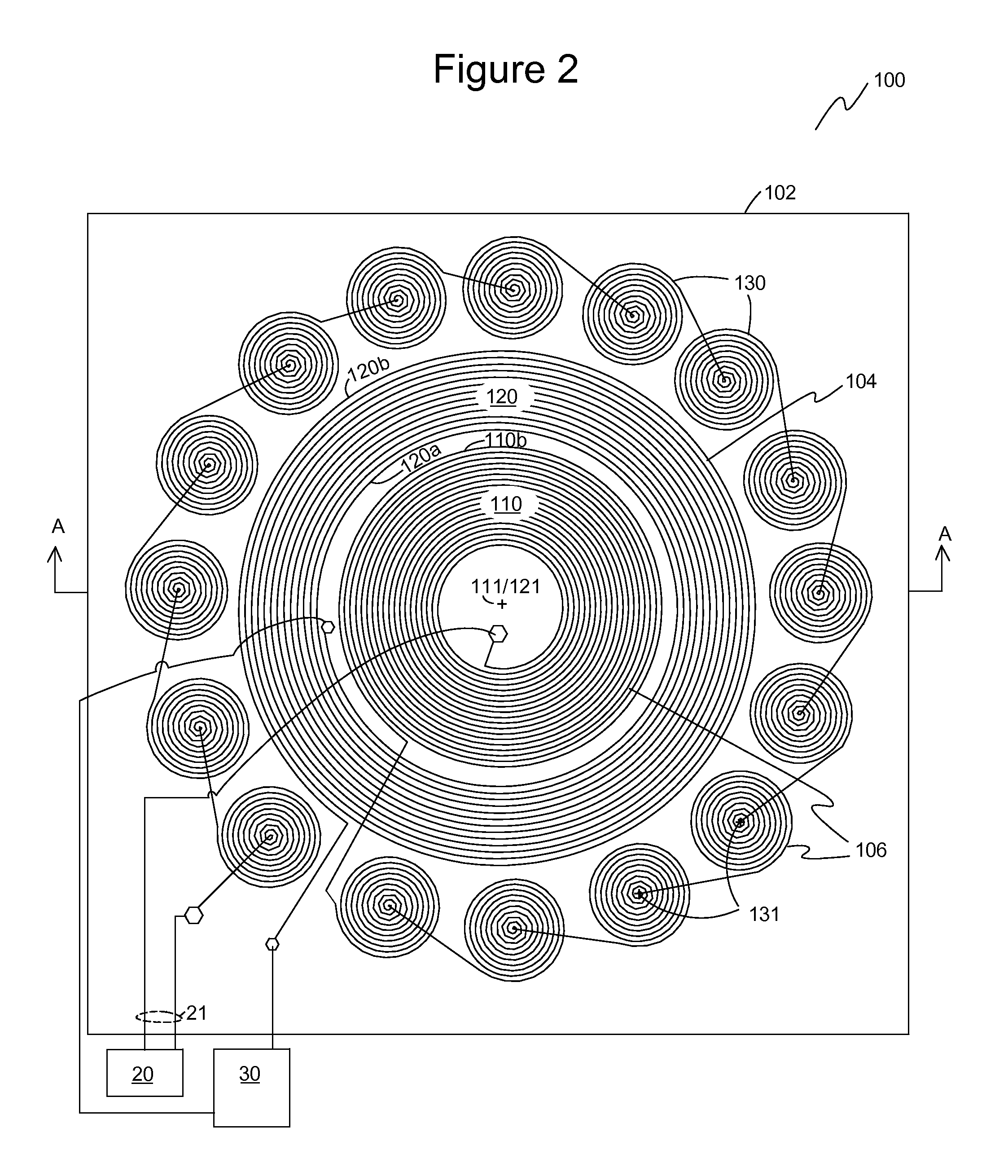
[0046]Exemplary embodiments of the present invention are illustrated in FIGS. 2-8. FIG. 2 shows a plan view of one embodiment of a transceiver antenna 100 of the present invention. Transceiver antenna 100 includes a transmit antenna 104 and a receive antenna 106. In one embodiment, transceiver antenna 100 has a substrate 102 upon which transmit antenna 104 and receive antenna 106 are disposed. For example, substrate 102 is a circuit board with transmit antenna 104 and receive antenna 106 disposed as conductive traces. Receive antenna 106 includes one or more inner receive coil(s) 110 and one or more outer receive coil(s) 130. The inner receive coil 110 is connected in series with the outer receive coils 130, which themselves are connected in series. Thus, all of the receive coils 110, 130 are connected in series.

[0047]In one embodiment as shown, receive antenna 106 has one inner receive coil 110 and a plurality of outer receive coils 130. In the embodiment shown, there are sixteen o...


PUM


Abstract

A transceiver antenna has a transmit antenna coil defining a substantially closed transmit coil geometry circumscribing a transmit coil inner area. The transmit antenna coil is configured to conduct a current to generate a magnetic field. One or more receive antenna coils each define a closed receive coil geometry with a number of coil turns. The receive antenna coils are positioned to define one or more inner areas located within the transmit antenna coil inner area and one or more outer areas located outside of the transmit antenna coil. The inner areas and the outer areas of the receive antenna coil(s) are configured so that a first voltage induced by the transmit magnetic field into the outer areas of the receive antenna coils is attenuated by a second voltage induced by the transmit magnetic field into the inner areas of the receive antenna due to phase cancellation.

Description

BACKGROUND OF THE INVENTION[0001]1. Field of the Invention[0002]The invention relates generally to antennas for communication and more specifically to a near-field magnetic communication antenna.[0003]2. Description of the Prior Art[0004]Magnetic near-field communication provides secure communications with uses that include but are not limited to access control, financial transactions, and security systems. Some systems for near-field communication use a transmit antenna and a separate receive antenna. Coupling of the transmit magnetic field to the receive antenna plagues these types of systems because the transmit signal voltage is orders of magnitude greater than the desired receive signal voltage. For example, in some systems, the transmit signal voltage is about 400 volts and the desired receive signal voltage is about one volt or less. Therefore, to avoid overloading the receiver circuitry, transmit / receive switches are currently used to isolate the receiver from the transmitte...

Claims


Application Information

Patent Timeline
IPC IPC(8): H01Q21/28H04B1/40H04B5/02H01Q7/00
CPCH01Q21/28H04B5/02H04B1/40H01Q7/00
Inventor HELBERS, JAN H.
Owner NEAR FIELD MAGNETICS
Why Eureka
Try Eureka