
Weight balancing face shield

a face shield and weight-balancing technology, applied in the direction of headwear caps, protective garments, goggles, etc., can solve the problems of no longer providing sufficient frictional force, tedious requirements can be distracting and sometimes dangerous tasks, and the tightening mechanism can become worn

Active Publication Date: 2013-05-07
PAULSON ROY
View PDF18 Cites 12 Cited by
  • Summary
  • Abstract
  • Description
  • Claims
  • Application Information

AI Technical Summary

Benefits of technology

The present invention is a device that includes a lens assembly that can be used as a protective shield for the face of a user. The lens assembly can be rotated from a vertical position to a stowed horizontal position on the user's headwear. The device also includes a means to ensure proper installation of the shield lens into its frame. This invention provides safety and protection for users in various situations where there may be flying objects or arc flashes.

Problems solved by technology

Such a tedious requirement can be a distracting and sometimes dangerous task especially when performing in hazardous environments such as welding or other metal work.
Similarly, the tightening mechanism can become worn to the point of no longer providing sufficient frictional force to maintain the shield in a secure position.
Further, the user can forget to tighten the mechanism and thereafter the shield can drop at a very inconvenient or even dangerous moment.
Unfortunately, this system is also prone to wear to the point of no longer being able to hold a secure position, which again can be distracting and dangerous to the user.
Along with the shortcomings described above, the simple hinge design itself fails in areas of comfort and ease of maneuverability for the user when the shield is in the upright horizontal position.
This causes uneven weight distribution and extraneous stress and strain on the user's neck.
Additionally, the loading of the weight of the shield, on the forward section of the helmet, can cause the helmet itself to rotate forward or fall off the user's head.
Further such uneven weight distribution can cause fatigue and even permanent neck damage as time goes on.
Similarly, it may be difficult for the wearer to move and work with this nuisance which is undesirable.
All these problems associated with conventional head and helmet mounted face shield systems can combine to cause users to resist or fail to employ their safety shields properly if they tire of the adjustments required or the improper balance causing them pain and inconvenience.
Such can lead to severe injury to the face and eyes of the user.
Although practical, this feature tends to inhibit air flow behind the shield and in front of the user's face.
This can in fact increase CO2 buildup within the confines of the shield and also can lead to fogging.
This lack of air flow thus introduces another safety hazard for the wearer and is therefore undesirable since the user cannot see through a fogged shield.
However, since the chin protectors are often supplied separately from the face shield manufacturer and then user-added, they may not be optimized at the same rating of arc protection as the shield itself, rendering the addition of the feature useless.

Method used


Image

  • Weight balancing face shield
  • Weight balancing face shield
  • Weight balancing face shield

Examples


Embodiment Construction

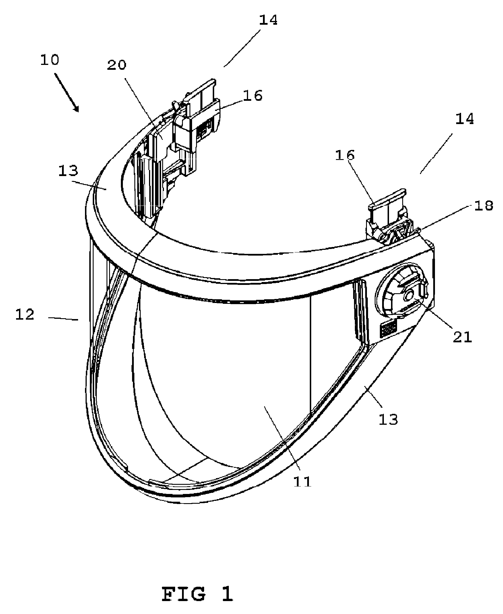
[0047]Now referring to drawings in FIGS. 1-10, wherein similar components are identified by like reference numerals, there is seen in FIG. 1 a mode of the device 10 having a front lens assembly 12 and rear hinge assemblies 14. The front lens assembly 12 is comprised of the protective transparent lens 11, a frame 13, and means for illumination shown as a light system 21. The light system 21 allows for engagement of a light source (not shown) that can be rotationally adjusted by the user.

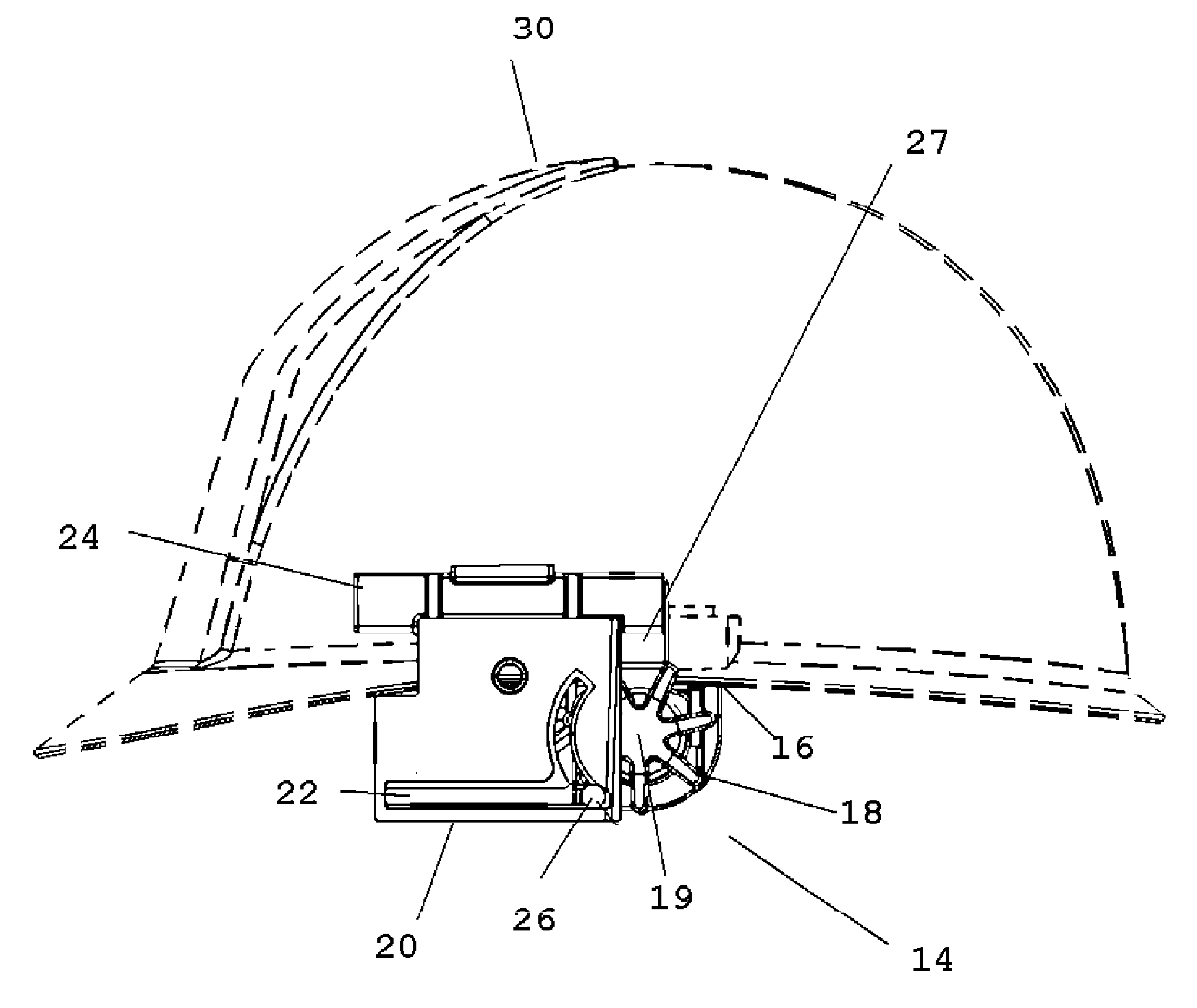
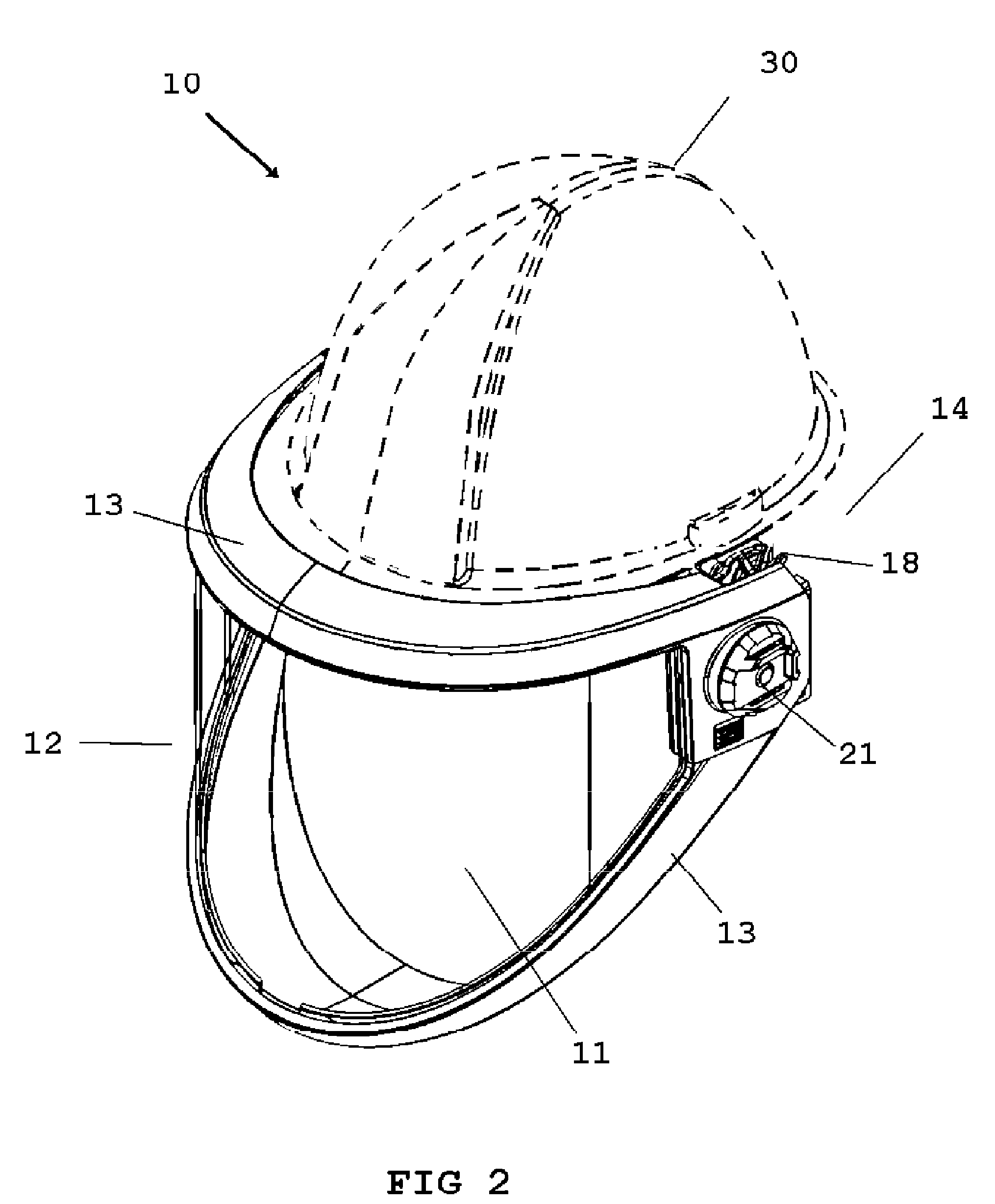
[0048]The hinge assemblies 14 contain helmet engagement adaptors 16 and a track system 20 noted in detail below. The adaptors 16 shown herein provide means for engagement of the device 10, to a helmet or the like, and are merely exemplar of one mode of such a means to engage the device 10 to a helmet 30 such as by adhesive to the interface provided by the adapter 16, (see FIG. 2), and may take on other forms such as clips or fasteners or the like as would occur to those skilled in the art. As such, an...


PUM


Abstract

A rotational engagement component to engage a lens for facial protection, to headwear such as a helmet worn on the head of a user. The device features one or a plurality of mounts engageable to the helmet. A pivot engaged with the mount and with the lens, allow rotation of the lens from an as-used position in front of the user, to a horizontal stowed position. The pivot is translatable in its engagement to the mount allowing for translation of the lens in the stowed position to adjust its center of gravity on the user's head.

Description

[0001]This application claims priority to U.S. Provisional Patent Application No. 61 / 390,986, filed on Oct. 7, 2010 and included herein in its entirety by this reference.BACKGROUND OF THE INVENTION[0002]1. Field of the Invention[0003]The disclosed invention relates generally to helmet or head-mounted face shields and guards. More specifically, it relates to an improved face shield adapted for engagement with a protective helmet which rotates the protective shield to a balanced retracted position when not being employed.[0004]2. Prior Art[0005]Whether working with heavy machinery, dangerous equipment or power tools, safety is always a concern. Face protection has always been important and comes in various forms such as goggles, shields, etc. Although goggles can be very beneficial to eye protection, when it comes to full face protection, such as in welding or operating machinery, a face covering shield is the more desirable choice.[0006]Commonly, face shields are mounted to a helmet ...

Claims


Application Information

Patent Timeline
Patent Type & Authority Patents(United States)
IPC IPC(8): A61F9/06
CPCA42B3/225
Inventor PAULSON, ROY
Owner PAULSON ROY
Learn More