Beam combining light source

a beam and light source technology, applied in the field of beam and light source, can solve the problems of long and thin emitting apertures, complicated assembly and alignment, and relatively bulky

Active Publication Date: 2013-05-07
LUMENTUM OPERATIONS LLC
View PDF28 Cites 43 Cited by
  • Summary
  • Abstract
  • Description
  • Claims
  • Application Information

AI Technical Summary

Problems solved by technology

However, light emitted from a high power single emitter diode laser is typically highly asymmetric due to a thin-slab geometry of the laser diodes resulting in long and thin emitting apertures.
One drawback of the device of Horikawa is that it is relatively bulky due to, at least in part, its essentially three-dimensional structure, which may also complicated assembly and alignment.
Another drawback is that dissipating heat from the laser diodes may be more complicated.
This arrangement, although conserving space occupied by the assembly, can disadvantageously complicate the optical alignment of individual elements in the assembly, and its overall fabrication.

Method used


Image

  • Beam combining light source
  • Beam combining light source
  • Beam combining light source

Examples


Embodiment Construction

[0032]While the present teachings are described in conjunction with various embodiments and examples, it is not intended that the present teachings be limited to such embodiments. On the contrary, the present teachings encompass various alternatives, modifications and equivalents, as will be appreciated by those of skill in the art. The terms “horizontal” and “vertical” are used exclusively with respect to the plane of the sheet. The terms “connect,”“couple,”“mount” and similar terms with their inflectional morphemes do not necessarily denote direct and immediate connections, but also include connections through mediate elements or devices.

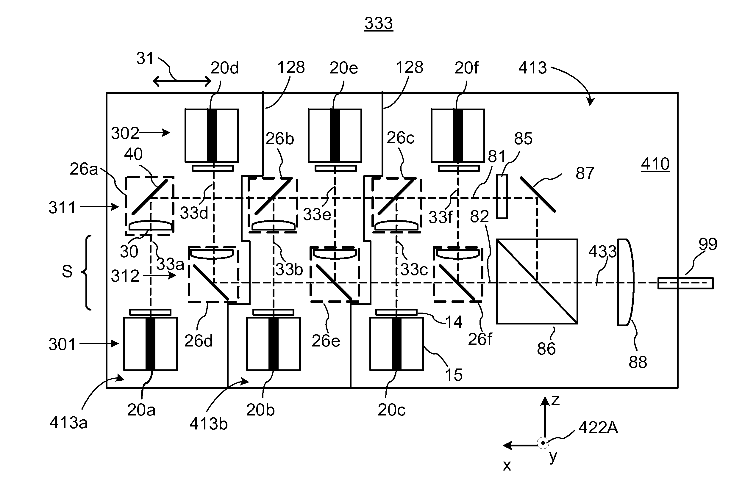
[0033]With reference to FIGS. 3A and 3B, there is shown, in plane and side views, respectively, one exemplary layout of an apparatus 222 for coupling radiation beams into an output port 99 such as an optical fiber or waveguide. The apparatus 222 will also be referred to herein as a beam combining optical source 222. The apparatus 222 is comprised ...


PUM

PropertyMeasurementUnit
diameteraaaaaaaaaa
diameteraaaaaaaaaa
widthaaaaaaaaaa

Abstract

The invention relates to sources of optical radiation wherein polarized radiation from first and second rows of light emitters is first collimated and combined into two combined beam using first and second rows of collimating and beam re-directing elements, respectively, and then polarization multiplexed to form a polarization-multiplexed output beam. In order to reduce the footprint, emitters of the first and second emitter rows are disposed in an interleaved, staggered arrangement, and the second row of collimating and beam re-directing elements is disposed in a space between the first emitter row and the first row of collimating and beam re-directing elements.

Description

CROSS-REFERENCE TO RELATED APPLICATIONS[0001]The present invention is a continuation-in-part of a U.S. patent application Ser. No. 12 / 827,946 filed Jun. 30, 2010, which is incorporated herein by reference for all purposes.TECHNICAL FIELD[0002]The present invention generally relates to sources of optical radiation wherein light from multiple emitters is combined into a single output beam, and more specifically relates to combining polarized light from multiple laser or light emitting diodes into a single output beam for coupling into an optical fiber or waveguide.BACKGROUND OF THE INVENTION[0003]Semiconductor laser diodes, manufactured as single emitter lasers or laser diode bars, have a high electrical-to-optical conversion efficiency, and can presently achieve optical power levels of a few Watts or even tens of Watts per single emitter laser diode, and tens to hundreds of Watts per laser diode bar. Due to high efficiency, reasonable power levels, and high spectral and directional b...

Claims


Application Information

Patent Timeline
Patent Type & Authority Patents(United States)
IPC IPC(8): G02B27/14
CPCH01S5/405H01S5/4012H01S5/005H01S5/02248H01S5/02284Y10T29/49826H01S5/4056H01S5/4075H01S5/02325H01S5/02251
Inventor DU, JIHUAGUO, JAMES YONGHONGXU, LEIDUESTERBERG, RICHARD L.SKIDMORE, JAY A.
Owner LUMENTUM OPERATIONS LLC
Why Eureka
Try Eureka