Combustor assembly for use in a turbine engine and methods of assembling same

a turbine engine and combustion assembly technology, applied in the field of turbine engines, can solve the problems of increasing the temperature within the combustion assembly, affecting the combustion performance of the combustion assembly,

Active Publication Date: 2013-05-14
GENERAL ELECTRIC CO
View PDF15 Cites 39 Cited by
  • Summary
  • Abstract
  • Description
  • Claims
  • Application Information

AI Technical Summary

Problems solved by technology

Such flame holding / flashback events may result in degradation of emissions performance, overheating, and / or damage to the fuel nozzle assembly.
Such eddies may increase the temperature within the combustion assembly and / or induce a screech tone frequency that induces vibrations throughout the combustor assembly and fuel nozzle assembly.
Over time, continued operation with increased internal temperatures and / or such vibrations may cause wear and / or may shorten the useful life of the combustor assembly.

Method used


Image

  • Combustor assembly for use in a turbine engine and methods of assembling same
  • Combustor assembly for use in a turbine engine and methods of assembling same
  • Combustor assembly for use in a turbine engine and methods of assembling same

Examples


Embodiment Construction

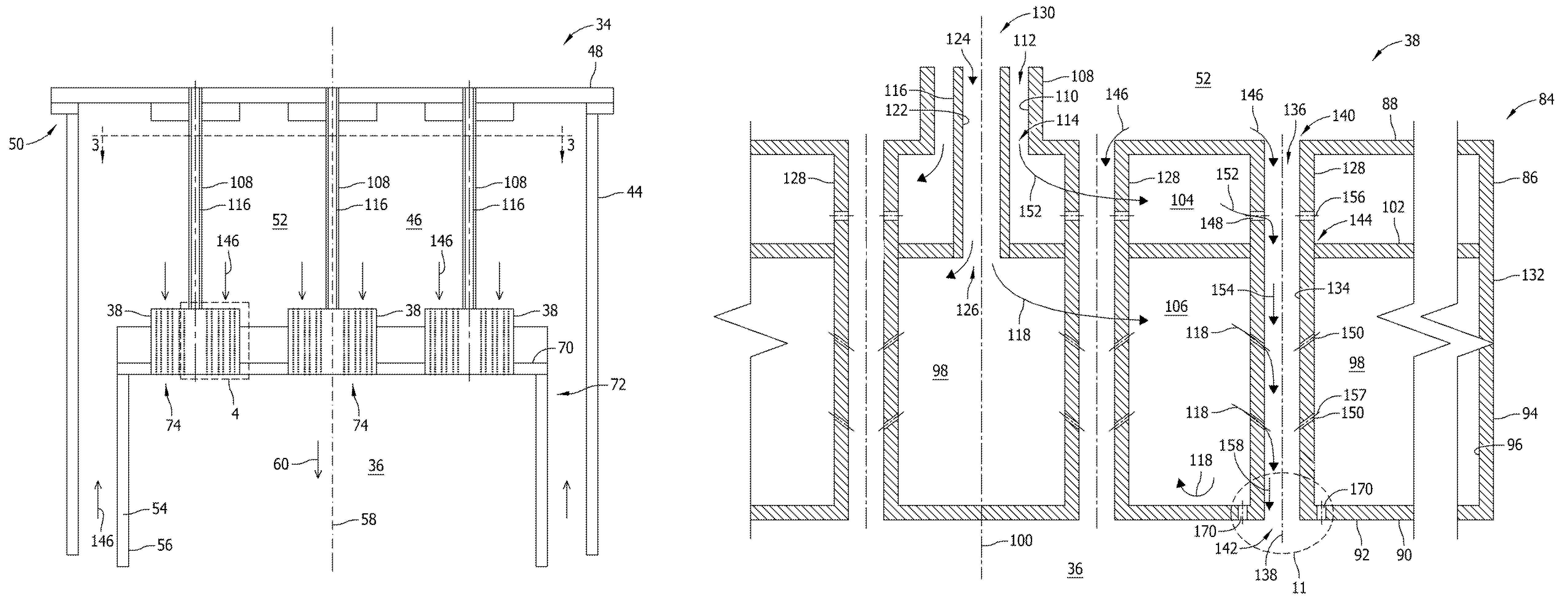
[0020]The exemplary methods and systems described herein overcome at least some disadvantages of at least some known combustor assemblies by providing a fuel nozzle assembly that includes a mixing tube that is coupled to a cooling fluid plenum that enables cooling fluid to be channeled through and / or around the mixing tube into a combustion chamber to facilitate reducing flame holding / flashback events and reduce NOX emissions. Moreover, the mixing tube includes a fuel aperture that enables fuel to be channeled into the mixing tube, and a cooling aperture that is downstream of the fuel aperture to enable cooling fluid to be channeled into the mixing tube such that a boundary layer is formed between the fuel mixture and the mixing tube. By channeling cooling fluid into the mixing tube downstream from the fuel mixture, the mixing tube facilitates reducing the probability of flame holding / flashback of the fuel nozzle. In addition, the fuel nozzle assembly includes a plurality of opening...


PUM


Abstract

A fuel nozzle assembly for use with a turbine engine is described herein. The fuel nozzle assembly includes a plurality of fuel nozzles positioned within an air plenum defined by a casing. Each of the plurality of fuel nozzles is coupled to a combustion liner defining a combustion chamber. Each of the plurality of fuel nozzles includes a housing that includes an inner surface that defines a cooling fluid plenum and a fuel plenum therein, and a plurality of mixing tubes extending through the housing. Each of the mixing tubes includes an inner surface defining a flow channel extending between the air plenum and the combustion chamber. At least one mixing tube of the plurality of mixing tubes including at least one cooling fluid aperture for channeling a flow of cooling fluid from the cooling fluid plenum to the flow channel.

Description

STATEMENT REGARDING FEDERALLY SPONSORED RESEARCH & DEVELOPMENT[0001]This invention was made with Government support under Contract No. DE-FC26-05NT42643, awarded by the Department of Energy. The Government has certain rights in this invention.BACKGROUND OF THE INVENTION[0002]The subject matter described herein relates generally to turbine engines and more particularly, to combustor assemblies for use in turbine engines.[0003]At least some known gas turbine engines ignite a fuel-air mixture in a combustor assembly to generate a combustion gas stream that is channeled to a turbine via a hot gas path. Compressed air is delivered to the combustor assembly from a compressor. Known combustor assemblies include a combustor liner that defines a combustion region, and a plurality of fuel nozzle assemblies that enable fuel and air delivery to the combustion region. The turbine converts the thermal energy of the combustion gas stream to mechanical energy used to rotate a turbine shaft. The out...

Claims


Application Information

Patent Timeline
Patent Type & Authority Patents(United States)
IPC IPC(8): F02C1/00
CPCF23R3/04F23R3/283F23R3/286F23R2900/00018F23D2209/20F23R2900/00014F23D2209/10F02C3/04F23R3/28
Inventor UHM, JONG HOJOHNSON, THOMAS EDWARD
Owner GENERAL ELECTRIC CO
Why Eureka
Try Eureka