Aircraft position light assembly

a technology for positioning lights and assembly parts, which is applied in the direction of landing aids, lighting and heating apparatus, and support devices, etc. it can solve the problems of inability to replace light modules, inability to adjust the position of lights, etc., to achieve the smallest possible physical footprint, maximize photometric performance, and optimize space usage

Active Publication Date: 2013-05-14
HONEYWELL INT INC
View PDF6 Cites 0 Cited by
  • Summary
  • Abstract
  • Description
  • Claims
  • Application Information

AI Technical Summary

Benefits of technology

[0002]Miniaturized forward position light universal module—LED—Meet FAA photometric requirements of aircraft forward position light using a universal, compact, LED module that can be installed in a variety of aircraft wing-tip cavities. Utilize a “blade” form factor to optimize space usage while maximizing photometric performance at historically weak areas of the FAA required angular intensity pattern.
[0003]The arrangement of the LEDs, reflectors, and light baffling surfaces allow for the smallest possible physical footprint and best possible performance at 90-degree vertical angular intensity points from an LED light module. Indirect-view reflector orientations maximize reflector light collection and redirection into critical portions of the angular intensity pattern while allowing direct-LED view to the wide-angle intensity zones (110-degrees horizontal and 90-degrees vertical).

Problems solved by technology

These light modules are unpredictable when they fail.
Thus, it can be expensive to have to replace these light modules at the time of failure, instead of at a preknown time for scheduling of such maintenance.
However, many of the existing LED systems are not designed to fit into existing light module housings, thereby making replacement of incandescent or halogen lamps with LEDs an expensive and time-consuming process.

Method used


Image

  • Aircraft position light assembly
  • Aircraft position light assembly
  • Aircraft position light assembly

Examples


Embodiment Construction

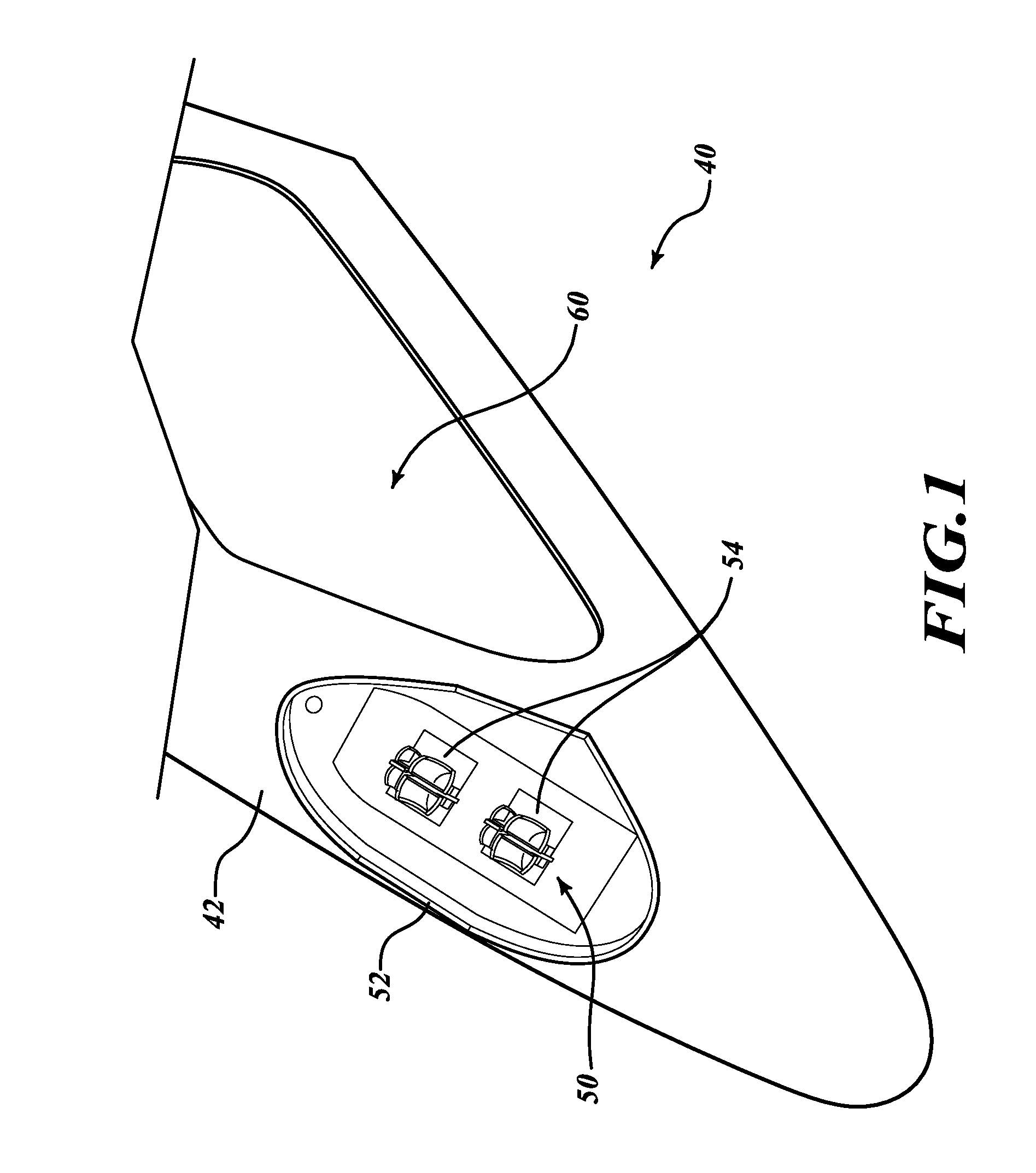
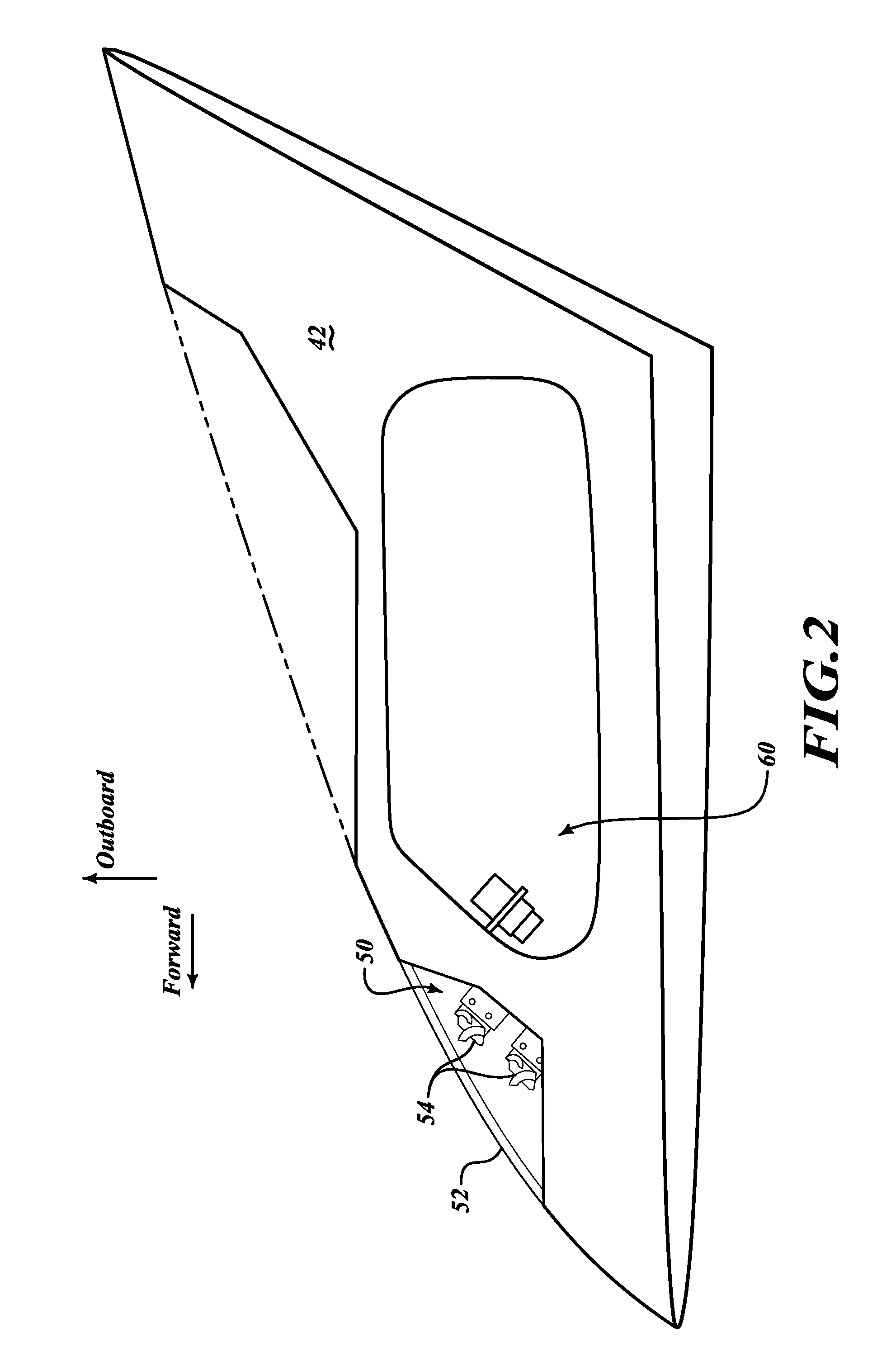
[0017]As shown in FIGS. 1-3, a wingtip assembly 40 includes a wing surface 42 with a cavity for housing position lights 50. The wingtip assembly 40 also includes an access panel 60. The position lights 50 are covered by a lens 52. The position lights 50 include two light-emitting diode (LED) modules 54. The LED modules 54 are mounted on a support base 70 that is rotatably attached to a support bracket 64 (see FIGS. 5-7).

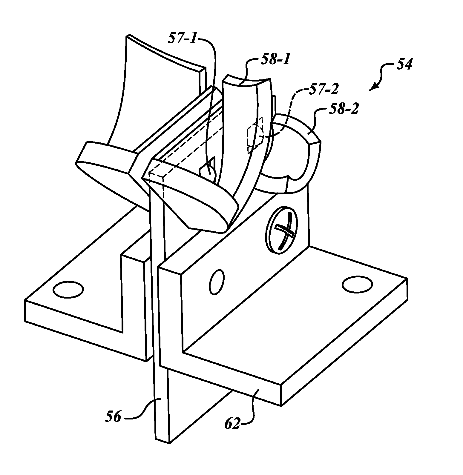
[0018]FIGS. 4-1, 4-2, 4-3 illustrate an exemplary LED module 54. The LED module 54 includes a circuit board 56 that includes two major surfaces. Each of the major surfaces includes metallic traces (not shown). Two or more metallic traces (not shown) are embedded within the circuit board 56. A single circuit board design may also be used.

[0019]A first reflector unit (forward 58-1 and aft 58-2) is mounted on the circuit board 56 at a first end. A second reflector unit is mounted on the circuit board 56 on the side of the circuit board 56 opposite the first reflector un...


PUM


Abstract

An aircraft position light assembly having one or more light emitting diode (LED) modules. The LED module can be installed in a variety of aircraft wing-tip cavities. An example LED module includes a support device that mounts within an aircraft wingtip, a bracket device that attaches to the support device, at least one circuit board that mounts to the bracket, and two pairs of LEDs. Each pair of LEDs is mounted on opposing major surfaces at a first end of the circuit board. A first pair of reflectors is attached to the circuit board adjacent to two of the LEDs on the opposing major surfaces. A second pair of reflectors is attached to the circuit board adjacent to the other two LEDs on the opposing major surfaces.

Description

BACKGROUND OF THE INVENTION[0001]Many large, commercial aircraft navigation lights use incandescent or halogen light modules. These light modules are unpredictable when they fail. Thus, it can be expensive to have to replace these light modules at the time of failure, instead of at a preknown time for scheduling of such maintenance. Light-emitting-diodes (LEDs) are slowly replacing navigation and position lights on commercial aircraft. Some of the benefits include longer life, lower power, lighter module packages, etc. However, many of the existing LED systems are not designed to fit into existing light module housings, thereby making replacement of incandescent or halogen lamps with LEDs an expensive and time-consuming process.SUMMARY OF THE INVENTION[0002]Miniaturized forward position light universal module—LED—Meet FAA photometric requirements of aircraft forward position light using a universal, compact, LED module that can be installed in a variety of aircraft wing-tip cavities...

Claims


Application Information

Patent Timeline
Patent Type & Authority Patents(United States)
IPC IPC(8): B60Q1/26
CPCB64D47/06B64C2027/8236B64D2203/00
Inventor STOUT, BOHOLDEN, TIMOTHY A.COLVIN, KENNETHWALKER, RICHARDLUNDBERG, JOHN
Owner HONEYWELL INT INC
Why Eureka
Try Eureka