

Punctal plugs
a technology of plugs and plugs, applied in the field of punctal plugs, can solve the problems of ineffectiveness, bleeding or perforation of the globe, ineffectiveness for some applications, and a large amount of drop
Active Publication Date: 2013-05-14
JOHNSON & JOHNSON VISION CARE INC
View PDF15 Cites 16 Cited by
- Summary
- Abstract
- Description
- Claims
- Application Information
AI Technical Summary
Benefits of technology
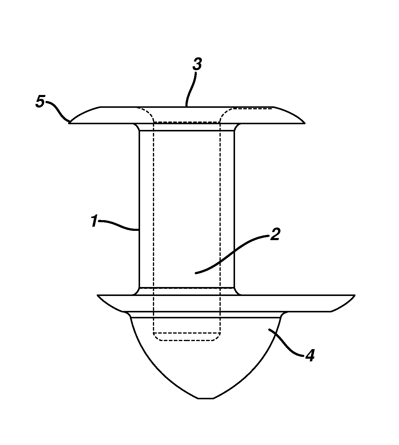
The invention is about punctal plugs used to treat certain eye conditions. These plugs have various features and advantages. One feature is that some punctal plugs have a body with a first end, a second end, and a lateral surface extending between the two ends. The lateral surface has an outer diameter that is substantially circular in shape, which makes it easier for the plug to stay in place. An anchor is affixed to the end of the body opposite the collarette, which helps keep the plug secure. The anchor has a cone shape and may be formed during the molding process. The punctal plugs also have an enlarged portion on the lateral surface that helps anchor them in the lacrimal canaliculus. This enlarged portion may have different shapes, such as an inverted triangle or a rounded body. Overall, the punctal plugs have improved stability and can provide better treatment outcomes for eye conditions.
Problems solved by technology
Active agents for ocular diseases and disorders may be administered orally or by injection, but such administration routes are disadvantageous in that, in oral administration, the active agent may reach the eye in too low a concentration to have the desired pharmacological effect and their use is complicated by significant, systemic side effects, while injections pose the risk of infection, discomfort, bleeding or perforation of the globe.
The majority of ocular active agents are currently delivered topically using eye drops which, though effective for some applications, are inefficient.
When a drop of liquid is added to the eye, it overfills the conjunctival sac, the pocket between the eye and the lids, causing a substantial portion of the drop to be lost due to overflow of the lid margin onto the cheek.
Method used
View moreImage
Smart ImageViewing Examples

Examples
example 1
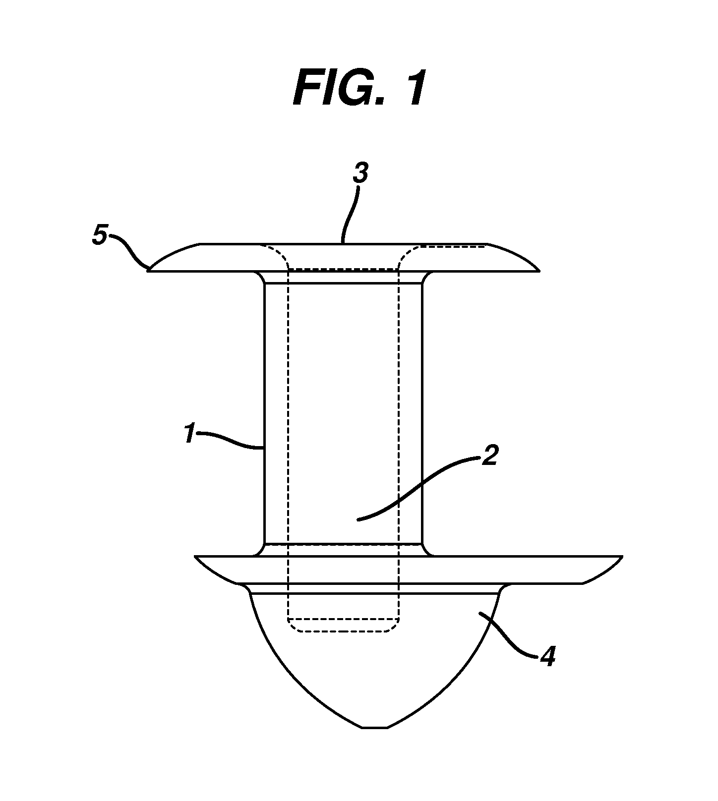
[0064]0.35 to 0.75 mg of a 2 part silicone rubber mixture with crosslinkers and catalyst obtained from Wacker Silicones, Adrian, Mich., were injected molded to form a punctal plug as shown in FIG. 2 The dimensions of the plug were as follows: the total length was 1.85 mm, the length of body 1.00 mm, diameter or radius of both the flange and arrowhead was 1.2 mm, the amount of offset from central axis was between 5 to 15 μm, there were between 2 to 5 threads with a bore diameter of about 0.4 mm.
[0065]Insertion and removal forces are summarized in Table 1:
[0066]
TABLE 1CorkyConeheadInsertion Force (N)0.220.18Time (sec)89Removal Force (N)0.170.12Time (sec)1417
Login to View More PUM
 Abstract
Punctal plugs for delivering therapeutic agents to the eye have a body with a portion into which the therapeutic agent is loaded and a conical anchor portion at an end of the plug.
Description
CROSS-REFERENCE TO RELATED APPLICATIONS[0001]This is a non-provisional application which claims priority to U.S. Provisional Application 61 / 165,413, filed Mar. 31, 2009. The aforementioned application is incorporated in full by reference herein.BACKGROUND OF THE INVENTION[0002]The present invention relates to devices suitable for delivering substances to one or more of the eye, nose and throat. In particular, the invention relates to punctal plugs for delivery of at least one active agent.[0003]Human tears are secreted by the lacrimal gland and flow across the surface of the eye to a shallow pool, known as the lacrimal lake, located where the eyelids come together at their inner ends. From there, the tears drain through small openings in each of the upper and lower eyelids, termed the superior lacrimal punctum and the inferior lacrimal punctum, respectively. From the superior and inferior puncta, the tears pass into each of the superior and inferior lacrimal canaliculus, respectivel...
Claims
Login to View More Application Information
Patent Timeline
 Patent Type & AuthorityPatents(United States)
IPC IPC(8): A61F9/00
CPCA61K9/0051A61F9/00772A61F9/0017
InventorLUST, VICTORPARNELL, SR., PHILLIP KINGMCATEER, VINCENT G.SCHWAM, BRIANCHAOUK, HASSAN
OwnerJOHNSON & JOHNSON VISION CARE INC