Medical delivery device with a protective member

a protective member and delivery device technology, applied in the field of delivery devices, can solve the problems of tissue luminal inflammation, tissue granulation, and significant limitations in the effective placement of the stent into the lumen of the patient, and achieve the effect of accurate deployment of the implantable devi

Active Publication Date: 2013-05-14
MERIT MEDICAL SYST INC
View PDF40 Cites 20 Cited by
  • Summary
  • Abstract
  • Description
  • Claims
  • Application Information

AI Technical Summary

Benefits of technology

[0011]The invention addresses the above needs and achieves other advantages by providing a delivery device for deploying an implantable device within a lumen. The inventive delivery device includes a protective member for insulating at least a portion of the outer tube from external forces, such as an operator's hand or from the patient's lumen. Insulating any portion of the outer tube from external forces reduces the likelihood of the outer tube being pinched and interfering with the movement between the inner and outer tubes and thus the accurate deployment of the implantable device.

Problems solved by technology

Vascular as well as nonvascular stenting has evolved significantly; unfortunately, there remain significant limitations with respect to effectively implanting the stents into a patient's lumen.
Improper installation can lead to several adverse complications including tissue luminal inflammation and tissue granulation.
Therefore, an impairment of the movement between the tubular members may adversely affect the accuracy of the stent release.
More specifically, some operators have a tendency to grasp the outer tubular member during use of the delivery device, which may impair the movement between the tubular members.
As another example, the tubular members may become pinched or otherwise interfered with due to the tortuous path that the delivery device may take within the patient's lumen or from the pressure of the walls of the patient's lumen.

Method used


Image

  • Medical delivery device with a protective member
  • Medical delivery device with a protective member
  • Medical delivery device with a protective member

Examples


Embodiment Construction

[0034]The present invention now will be described more fully hereinafter with reference to the accompanying drawings, in which some, but not all embodiments of the invention are shown. Indeed, this invention may be embodied in many different forms and should not be construed as limited to the embodiments set forth herein; rather, these embodiments are provided so that this disclosure will satisfy applicable legal requirements. Like numbers refer to like elements throughout.

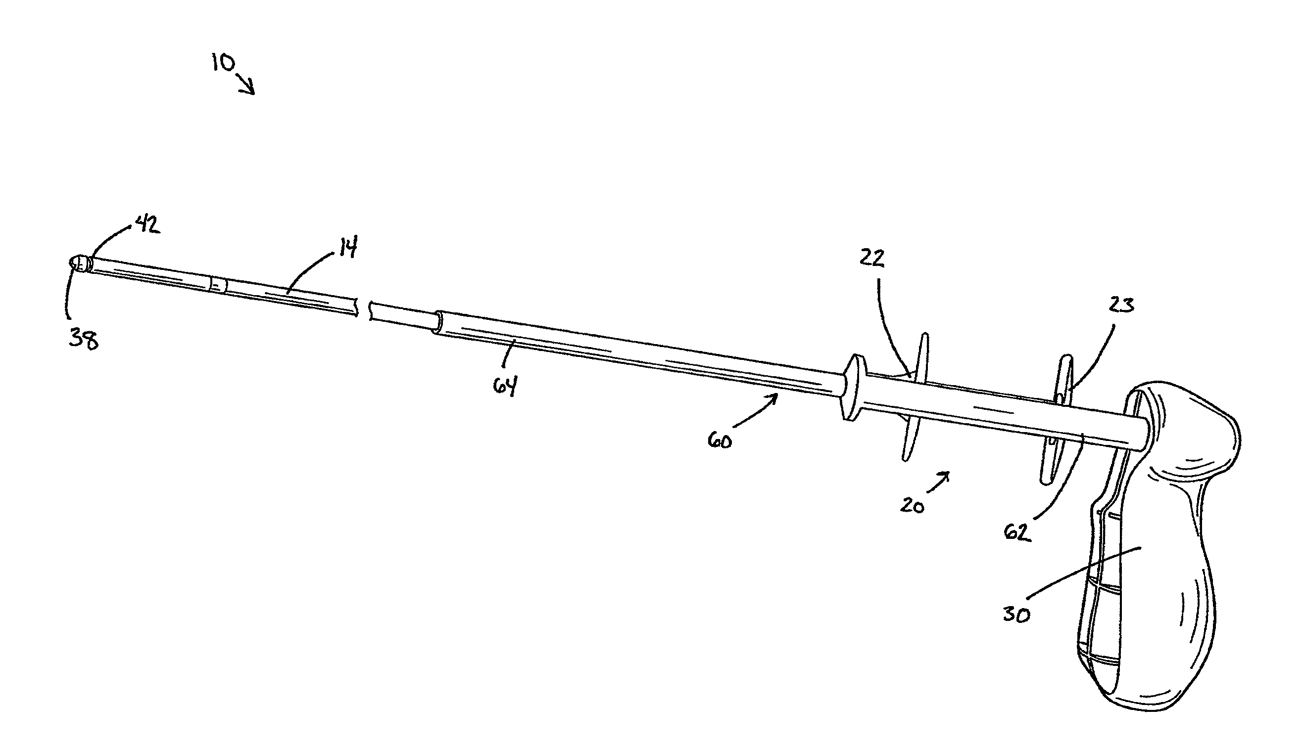
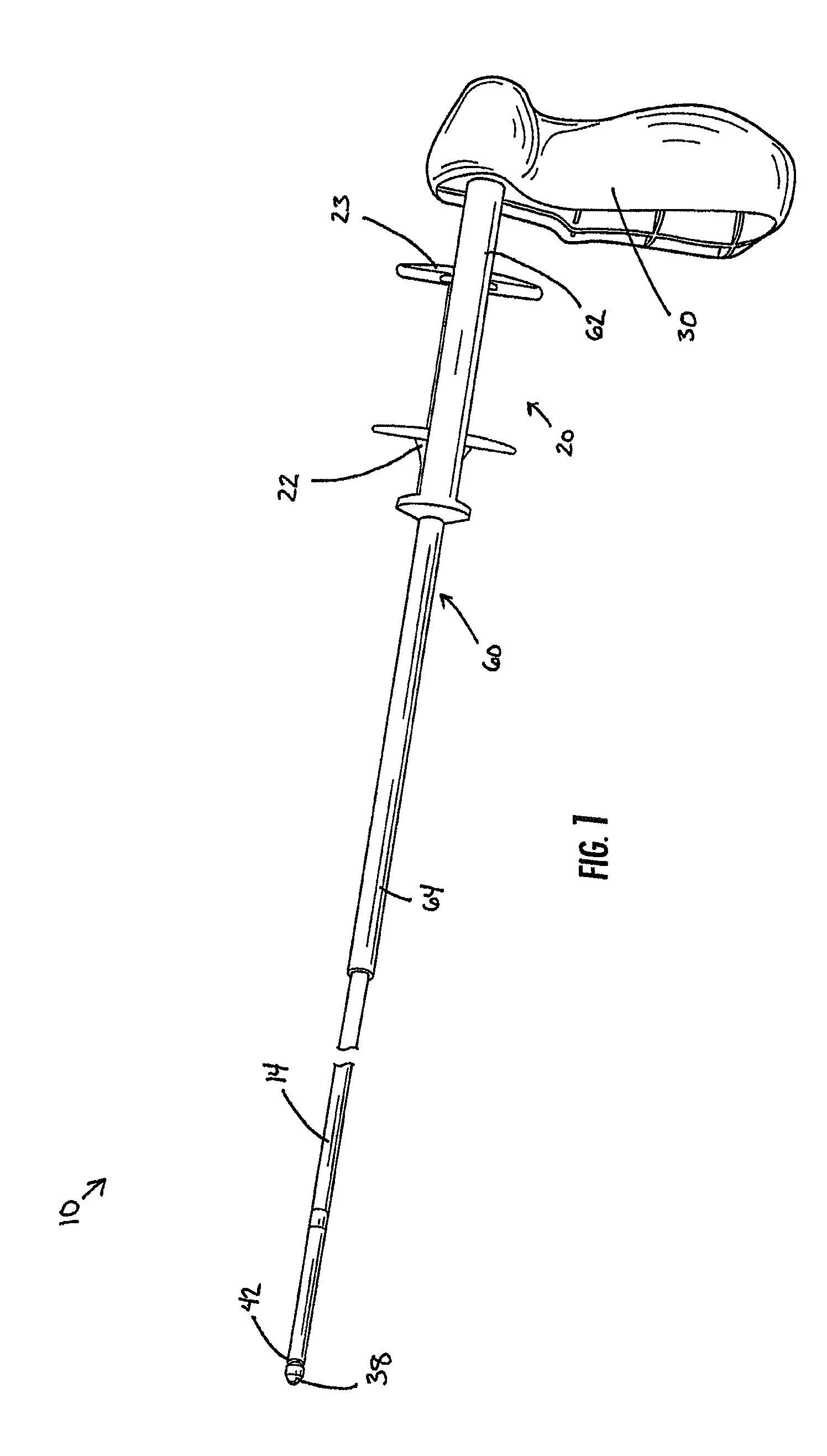
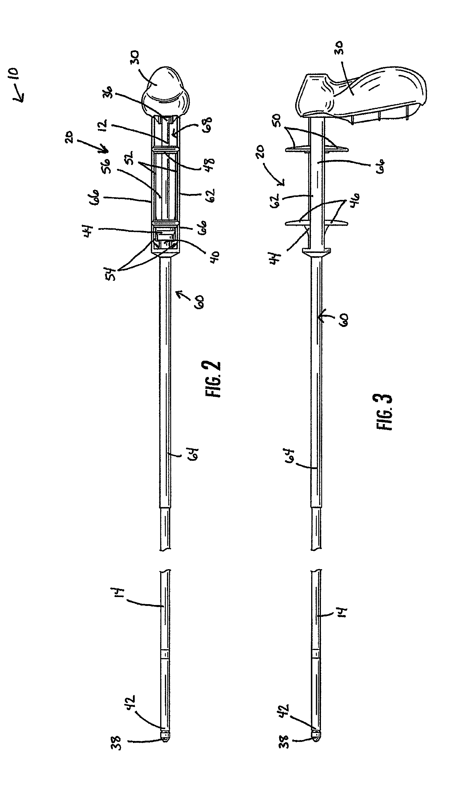
[0035]Embodiments of the present invention provide a delivery device 10 capable of being deployed within a lumen proximate to a target area. “Target area,” as used herein, is not meant to be limiting, as the target area, could be a stricture, lesion, tumor, occlusion, fistulae, or other complication where the lumen passageway has been significantly reduced. The delivery device 10 is typically utilized to deploy an implantable device (not illustrated) within a lumen. However, the delivery device 10 is also capable ...


PUM


Abstract

A delivery device for positioning and deploying an implantable device within a lumen is provided. The delivery device includes inner and outer tubular members slidable to each other between at least a first hold position and a second release position, a handle and a deployment mechanism adapted for an operator to use a first hand for operating the delivery device and moving the tubular members between the first and second positions. The delivery device further includes a protective member adapted for insulating at least a portion of the outer tubular member from the tendency of the operator to use his or her second hand to grab the outer tubular member during operations or from other external forces.

Description

CROSS REFERENCE TO RELATED APPLICATIONS[0001]This application claims the benefit of U.S. Provisional Application No. 61 / 090,139, filed Aug. 19, 2008, which is incorporated by reference herein in its entirety.BACKGROUND OF THE INVENTION[0002]1) Field of the Invention[0003]The present invention relates to a delivery device and to a delivery device for positioning and deploying an implantable device within a lumen.[0004]2) Description of Related Art[0005]Implantable medical devices are valuable tools of modern medicine. In general, an implantable device is a device or structure configured to be inserted or embedded into a patient for a variety of functions. Implantable devices include stents, filters, markers, drug delivery devices, valves, and monitors.[0006]In particular, stents are implantable devices that are inserted into body lumina such as vessels or passages to keep the lumen open and prevent closure due to a stricture, external compression, or internal obstruction. Stents are ...

Claims


Application Information

Patent Timeline
Patent Type & Authority Patents(United States)
IPC IPC(8): A61F2/95A61F2/04
CPCA61F2/95A61F2/966A61F2002/047A61F2002/9517A61F2/9517
Inventor SATASIYA, PANKAJWEBB, WILLIAMREYNOLDS, JASONSNIDER, ROBERT R.
Owner MERIT MEDICAL SYST INC
Why Eureka
Try Eureka