Modular adaptation and configuration of a network node architecture

a network node and module technology, applied in the field of module adaptation and configuration of network node architectures, can solve the problems of inability to easily reconfigure the regenerator node to provide add/drop functionality or terminal node operations, and the terminal node cannot be easily reconfigured to operate as a regenerator node, so as to reduce the requirement for cabling, increase reliability, and cost-effective low-power design

Active Publication Date: 2013-05-14
INFINERA CORP
View PDF11 Cites 3 Cited by
  • Summary
  • Abstract
  • Description
  • Claims
  • Application Information

AI Technical Summary

Benefits of technology

[0021]The base chassis architecture minimizes the requirement for cabling or optical interfaces, resulting in a more cost effective low power design, while increasing reliability. Costs can be further decreased through other design advances such as the use of integrated photonics, making the digital nodes more affordable. Another advantage is that the node may be dynamically adapted and / or configured in real-time during actual operation of the node. This dynamic adaptation may include converting a first type of node to a second type of node without interrupting service, stopping the operation of the node and unaffected paths within the node are not disturbed. For example, a regeneration node may be converted to an add / drop node without shutting the node down during this conversion process.
[0022]Any WDM transmission path may not be unaffected by the conversion process of a node within that path because the signal re-direction occurs only within the electrical domain. As a result, a WDM path may not be disturbed as potential add / drop functionality on a regenerator node within the path is being re-configured or otherwise changed. This feature allows an optical path to be activated and / or monitored for a period of time before an add / drop circuit is provisioned or the node re-configured without prior knowledge to future node configurations.

Problems solved by technology

As a result, a regenerator node may not be easily reconfigured to provide add / drop functionality or terminal node operations.
Comparatively, a terminal node may not be easily reconfigured to operate as a regenerator node.

Method used


Image

  • Modular adaptation and configuration of a network node architecture
  • Modular adaptation and configuration of a network node architecture
  • Modular adaptation and configuration of a network node architecture

Examples


Embodiment Construction

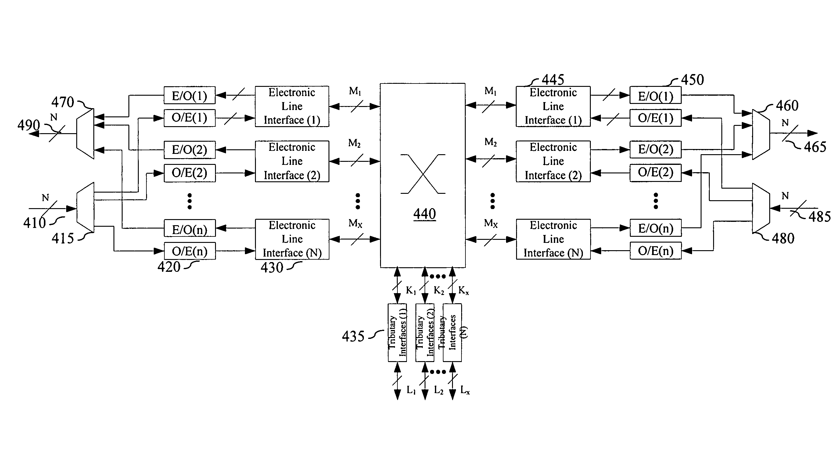
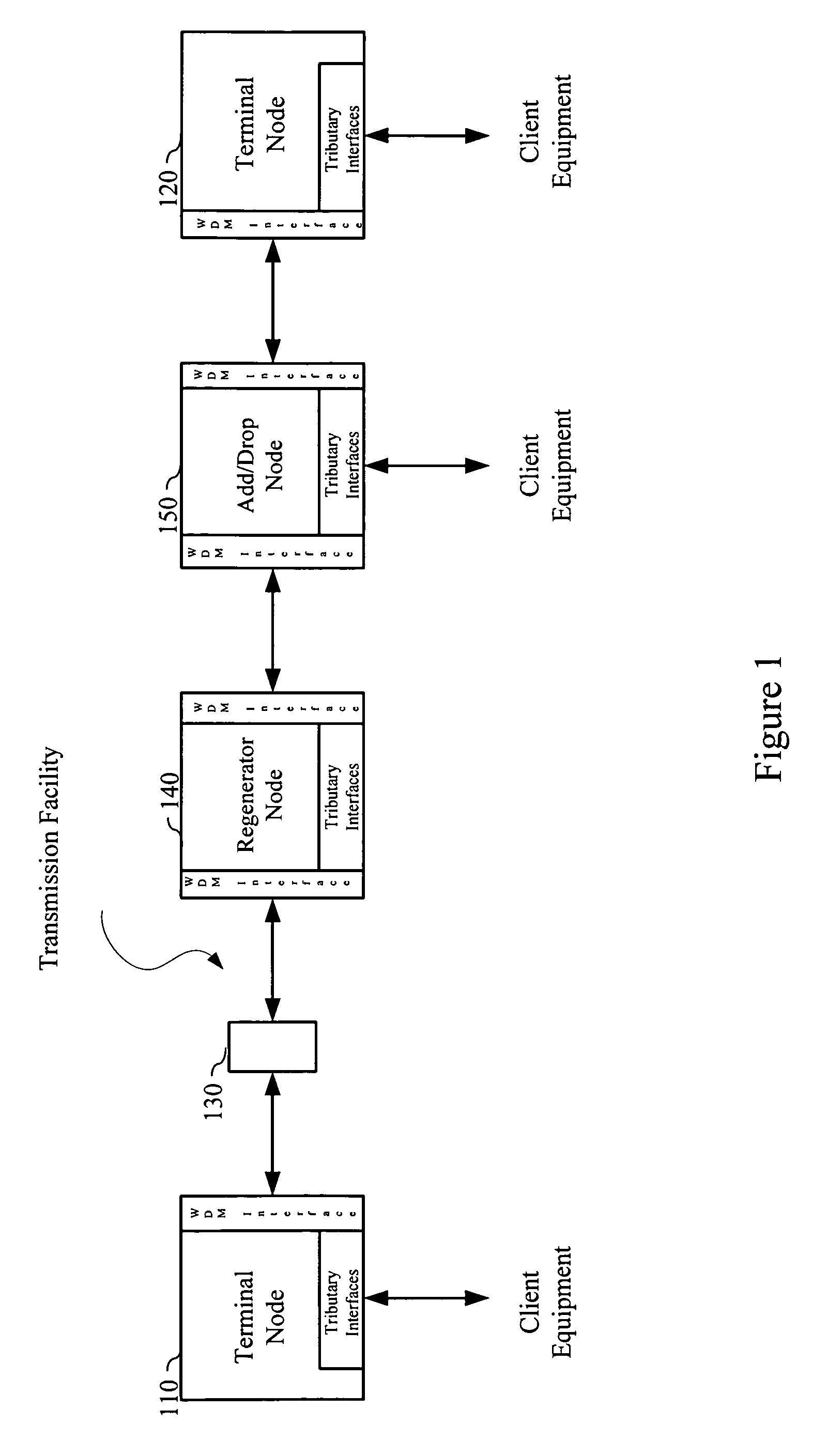
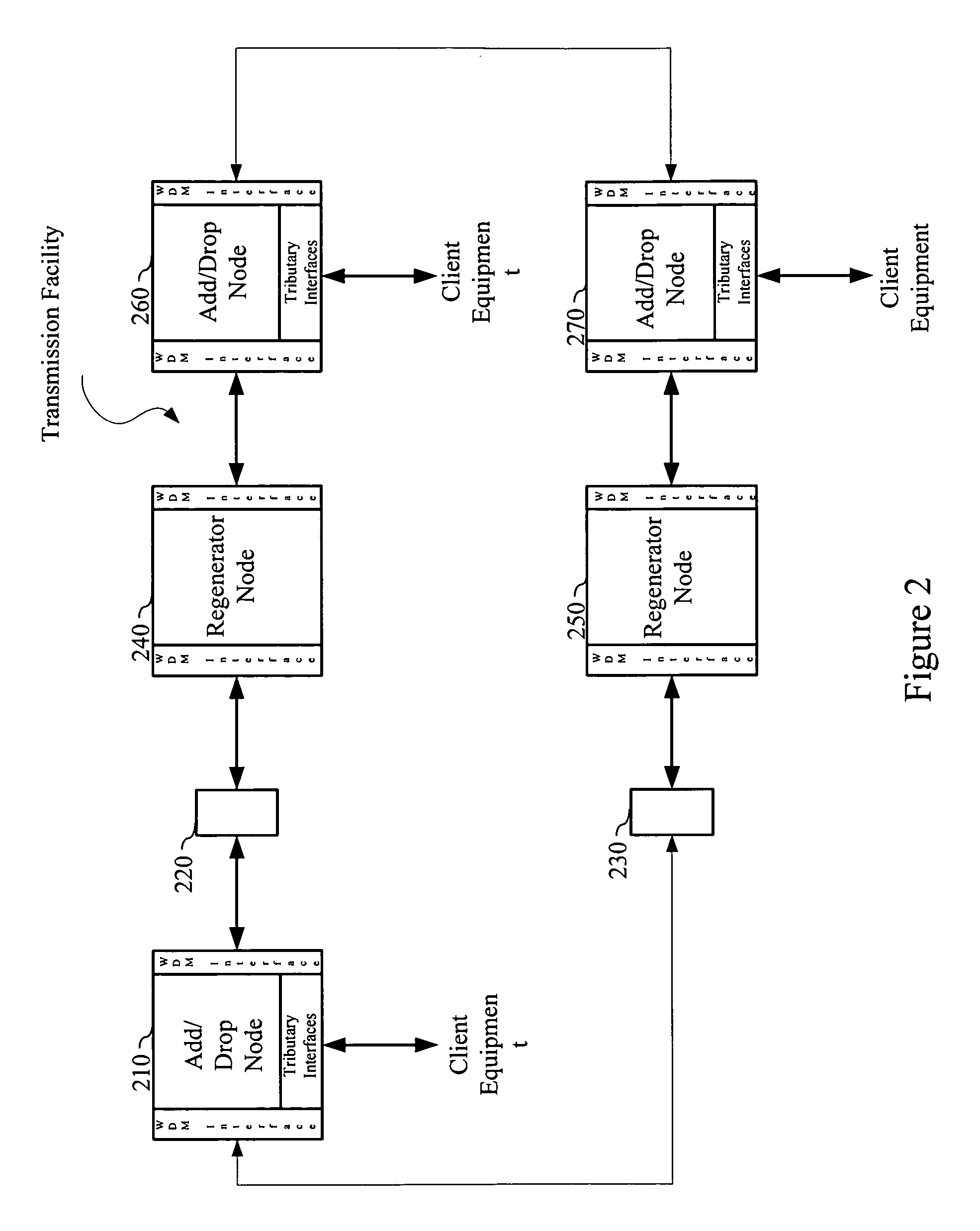
[0033]The present invention provides a system, apparatus and method for modularly adapting a network node architecture to function in one of a plurality of potential node types. The architecture includes a configurable switching element, and a plurality of modules, potentially having integrated optics and various types of interfaces, which allow an architectural configuration of the node to be adapted within the base architecture. The module interfaces may be optical or electrical and be used to construct various different types of nodes including regenerators, add / drop nodes, terminal nodes, and multi-way nodes using the same base architecture.

[0034]The following description is set forth for purpose of explanation in order to provide an understanding of the invention. However, it is apparent that one skilled in the art will recognize that embodiments of the present invention, some of which are described below, may be incorporated into a number of different computing systems and dev...


PUM


Abstract

The present invention provides a system, apparatus and method for modularly adapting a network node architecture to function in one of a plurality of potential node types. The architecture includes a configurable switching element, integrated optics, and a plurality of modules that allow a “type” of node to be adapted and configured within the base architecture. The module interfaces may be optical or electrical and be used to construct various different types of nodes including regenerators, add / drop nodes, terminal nodes, and multi-way nodes using the same base architecture.

Description

CROSS REFERENCE TO RELATED PATENT APPLICATIONS[0001]This application claims priority to U.S. Provisional Application Ser. No. 60 / 695,507, entitled “WDM Transport Node with Flexible Node Adaptation and Multiway Switching Capability,” filed Jun. 30, 2005, which application is incorporated herein by reference in its entirety.[0002]This application is related to U.S. Nonprovisional Patent Application Ser. No. 10 / 267,212, entitled “Digital Optical Network Architecture, filed Oct. 8, 2002; U.S. Nonprovisional Patent Application Ser. No. 10 / 715,947, entitled “Optical Transmission Network with Asynchronous Mapping and Demapping and Digital Wrapper Frame for the Same,” filed Nov. 18, 2003; U.S. Nonprovisional Patent Application Ser. No. 11 / 154,455, entitled “Universal Digital Framer Architecture for Transport of Clierit Signals of any Client Payload and Format Type,” filed Jun. 16, 2005, all of which are incorporated herein by reference in their entirety.BACKGROUND[0003]A. Technical Field[00...

Claims


Application Information

Patent Timeline
Patent Type & Authority Patents(United States)
IPC IPC(8): H04L12/50
CPCH04J14/0201H04L49/405H04L49/40H04J14/0219H04L49/45
Inventor PERKINS, DREW D.CHIANG, TING-KUANGSOSA, MARCO E.YIN, MARKSPRAGUE, EDWARD E.
Owner INFINERA CORP
Why Eureka
Try Eureka