Miniature safe and arm (S and A) mechanisms for fuzing of gravity dropped small weapons

a small weapon and gravity drop technology, applied in the field of small weapon systems, can solve the problems that the same cannot be said regarding ordnance technologies that support system functional capabilities, and the simple miniaturization of subsystems alone cannot achieve the desired effect of effective fuzing for small weapons, and achieve the effects of reducing collateral damage, low cost, and piezoelectric bas

Inactive Publication Date: 2013-05-21
OMNITEK PARTNERS LLC
View PDF16 Cites 8 Cited by
  • Summary
  • Abstract
  • Description
  • Claims
  • Application Information

AI Technical Summary

Benefits of technology

[0015]The mechanisms based on piezoelectric elements can provide electrical energy and release event indication signal almost instantaneously (2-3 msec) upon release to power fuzing electronic and logics circuitry, thereby making them highly suitable for weapons dropped from almost any altitude, even very high and very low altitudes; by employing a simple “distributed” piezoelectric element design, in addition to the target impact event detection, the impact force level (hard or soft target) and its direction may be determined and used for various fuzing purposes as well as for self-destruct or disarming purposes to reduce collateral damage and creation of UXOs.
[0016]The piezoelectric-based generators can be relatively small and low cost since they are constructed with off-the-shelf components. The overall packaging electronic and logics circuitry and the power generation devices can be very small and low cost since they can be produced using standard manufacturing techniques and components.

Problems solved by technology

However, the same cannot be said regarding ordnance technologies that support system functional capabilities, for example for the case for fuzing.
It is important to note that simple miniaturization of subsystems alone will not achieve the desired goal of effective fuzing for smaller weapons.

Method used


Image

  • Miniature safe and arm (S and A) mechanisms for fuzing of gravity dropped small weapons
  • Miniature safe and arm (S and A) mechanisms for fuzing of gravity dropped small weapons
  • Miniature safe and arm (S and A) mechanisms for fuzing of gravity dropped small weapons

Examples


Embodiment Construction

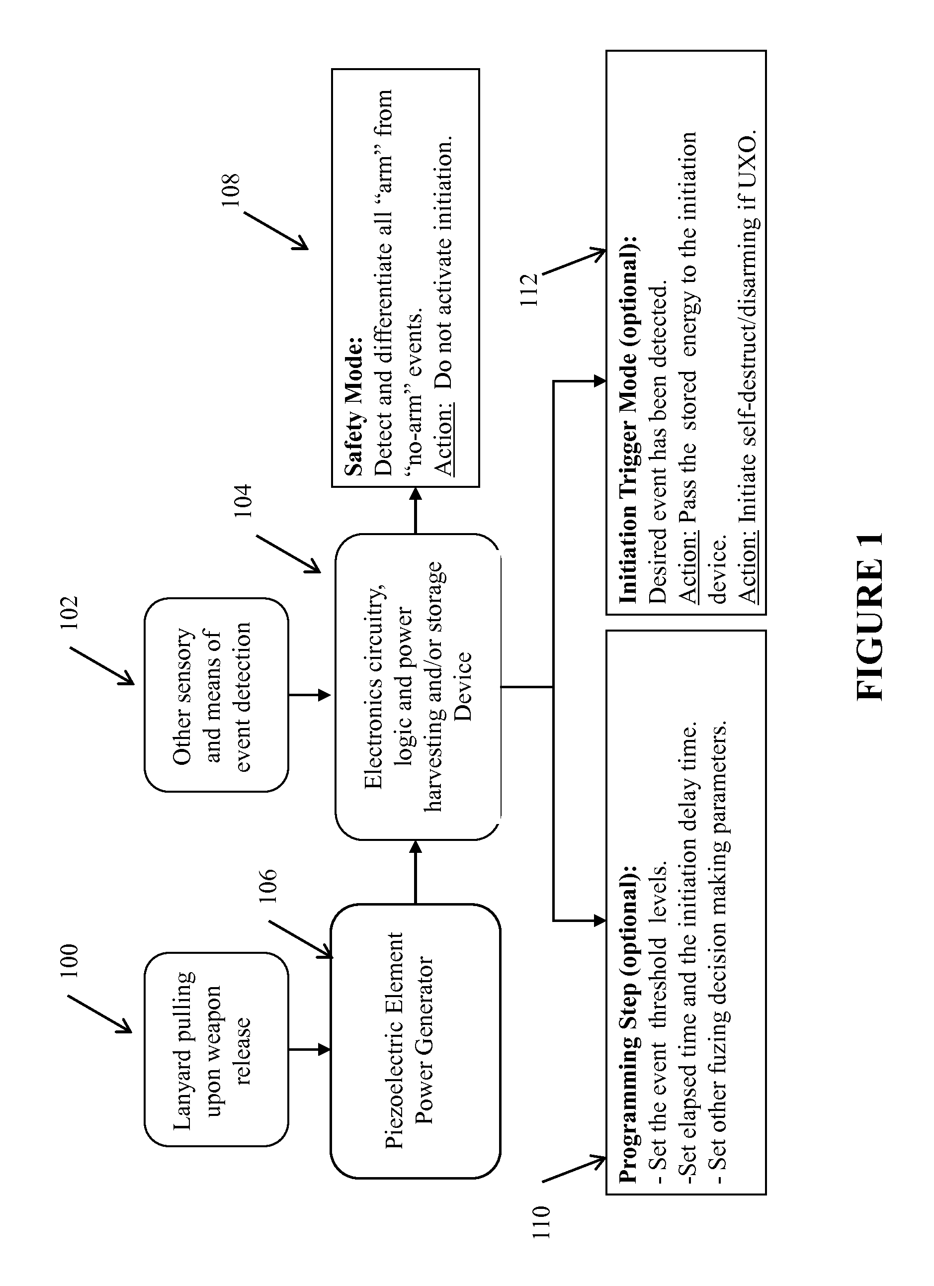
[0040]A block diagram representing a design of the devices for providing “safe” and “arm” (S&A) functionalities as well other possible fuzing functionalities is shown in FIG. 1. In FIG. 1, a detonation step is also provided for the sole purpose of indicating how a fuzing functionality such as detonation of initiation charges may also be achieved.

[0041]The devices can use piezoelectric-based power generators described below. The piezoelectric generators begin to produce power upon weapon release by the pulling of the lanyard 100. Other sensory devices and means can be used for the event detection 102. Each of the lanyard pulling and other sensory output is input to electronics circuitry logic and power harvesting and storage 104. The piezoelectric element of the power generator 106 can be pre-loaded to prevent it from generating a significant amount of energy that could otherwise power the device electronics as a result of accidental dropping or due to transportation induced vibrator...


PUM


Abstract

A device for enabling safe / arm functionality in a gravity dropped weapon detachably connected to an airframe where the device includes: an elastic element disposed in a shell of the weapon; a releasable connection between the weapon and the airframe to release one or more of a stored and generated energy in the elastic element; and a piezoelectric member connected to one end of the elastic member for converting the one or more of the stored and generated energy to an electrical energy. The releasable connection can include: a link having a movable connection for movement of the link relative to the shell between a first position constraining the elastic element from movement and a second position releasing the elastic member to generate the electrical energy; and a lanyard for tethering the link to the airframe such that the link is moved to the second position upon the weapon being released from the airframe.

Description

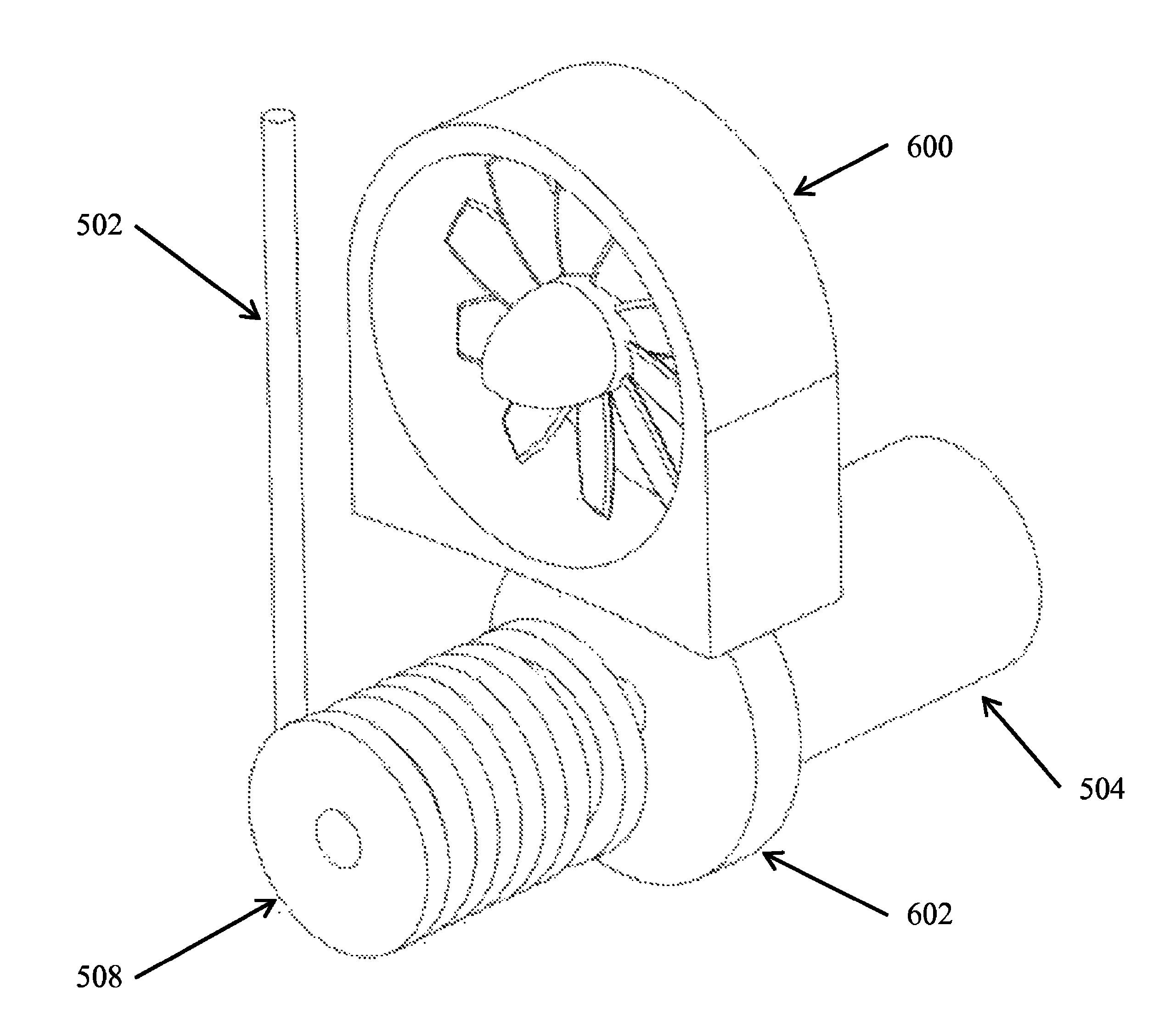
CROSS-REFERENCE TO RELATED APPLICATIONS[0001]This application claims benefit to U.S. Provisional Application No. 61 / 303,294 filed on Feb. 10, 2010, the entire contents of which is incorporated herein by reference. This application is related to U.S. patent application Ser. No. 12 / 606,893 filed on Oct. 27, 2009, the entire contents of which is incorporated herein by reference.GOVERNMENT RIGHTS[0002]This invention was made with government support under contract no. FA8651-09-M-0106 awarded by the United States Air Force. The government has certain rights in the invention.BACKGROUND OF THE INVENTION[0003]1. Field of the Invention[0004]The present invention relates generally to small weapon systems, and more particularly, to methods for enabling safe / arm functionality within small weapons.[0005]2. Prior Art[0006]All weapon systems require fuzing systems for their safe and effective operation. A fuze or fuzing system is designed to provide, as a primary role, safety and arming functions ...

Claims


Application Information

Patent Timeline
Patent Type & Authority Patents(United States)
IPC IPC(8): F42C11/00
CPCF42C15/40F42C14/06F42C11/02F42B25/00F42C15/20
Inventor RASTEGAR, JAHANGIR S.MURRAY, RICHARD T.
Owner OMNITEK PARTNERS LLC
Why Eureka
Try Eureka