Graded resistance solid state current control circuit

a solid-state current control and resistance technology, applied in the direction of contact mechanisms, emergency protective circuit arrangements, etc., can solve the problems of preventing the circuit breaker upstream from the fault from opening, collapsing, and reducing the accuracy of detection

Active Publication Date: 2012-09-27
SPD ELECTRICAL SYST
View PDF2 Cites 11 Cited by
  • Summary
  • Abstract
  • Description
  • Claims
  • Application Information

AI Technical Summary

Benefits of technology

[0013]The criteria regarding the time to interrupt the current are dependent upon two conditions. First, that the interruption time is so short that the loss of voltage during the fault will not jeopardize the operation of loads on adjacent circuits and, second, that the magnitude of the fault current will not jeopardize the integrity of the power electronics. This enhances the survivability of loads being fed by adjacent circuits and effectuates a tremendous reduction in collateral damage caused by a fault.
[0021]The power node switching center is a device which will distribute, switch and control power at electrical power nodes whose power handling capacity ranges from 0.5 MW to 50 MW, while accurately detecting downstream system faults and stopping the current flow in less then 400 microseconds.

Problems solved by technology

In the event of a fault, a prior art system may permit a high fault current, which has a potential for catastrophic collateral damage and which may also deprive other loads on the same or upwardly connected nodes of energy.
When a fault occurs in the prior art system, a circuit breaker upstream from the fault opens.
This perturbation is usually exhibited by a significant drop in voltage, particularly in close proximity to the fault, which may result in the voltage dropping to near zero for the period of time between the occurrence of the fault and the opening of the circuit breaker.
Sensitive loads may malfunction and some loads may become disconnected or may need to be reset or rebooted, causing them to be offline for a period of time significantly longer than the actual fault.
This is obviously undesirable for sensitive and critical loads.
Other loads may be transferred to alternate sources, which may cause further disturbances to the electrical system.
In addition, there may be substantial arcing at the point of fault while the electromechanical circuit breaker is opening.
The 6 loads in power panel #4 will be lost because the cable feeding them is faulted.
One problem with this configuration is that the inductive energy stored in the source and load inductances must be dissipated in the interrupting switch in order to bring the circuit current to zero.
As interruption time increases, the inductive voltage decreases, but the switch is forced to carry current while dropping the source voltage and so dissipates more energy.
The switch can be destroyed either by excessive voltage or excessive dissipation (heating).
The resistor thus ends up dissipating the circuit energy.
One problem with this configuration, however, is that, in high power circuits, the size, weight and cost of these components is significant and therefore poses an important impediment to market acceptance.
Varistors are generally smaller than passive snubbers, but repeated operation deteriorates performance and the limited, and somewhat unpredictable, life of the device is a major impediment to broad application.
The addition of a series switch improves life and reliability but with the penalty of another active component together with all the controls and auxiliaries necessary to operate it.

Method used


Image

  • Graded resistance solid state current control circuit
  • Graded resistance solid state current control circuit
  • Graded resistance solid state current control circuit

Examples


Embodiment Construction

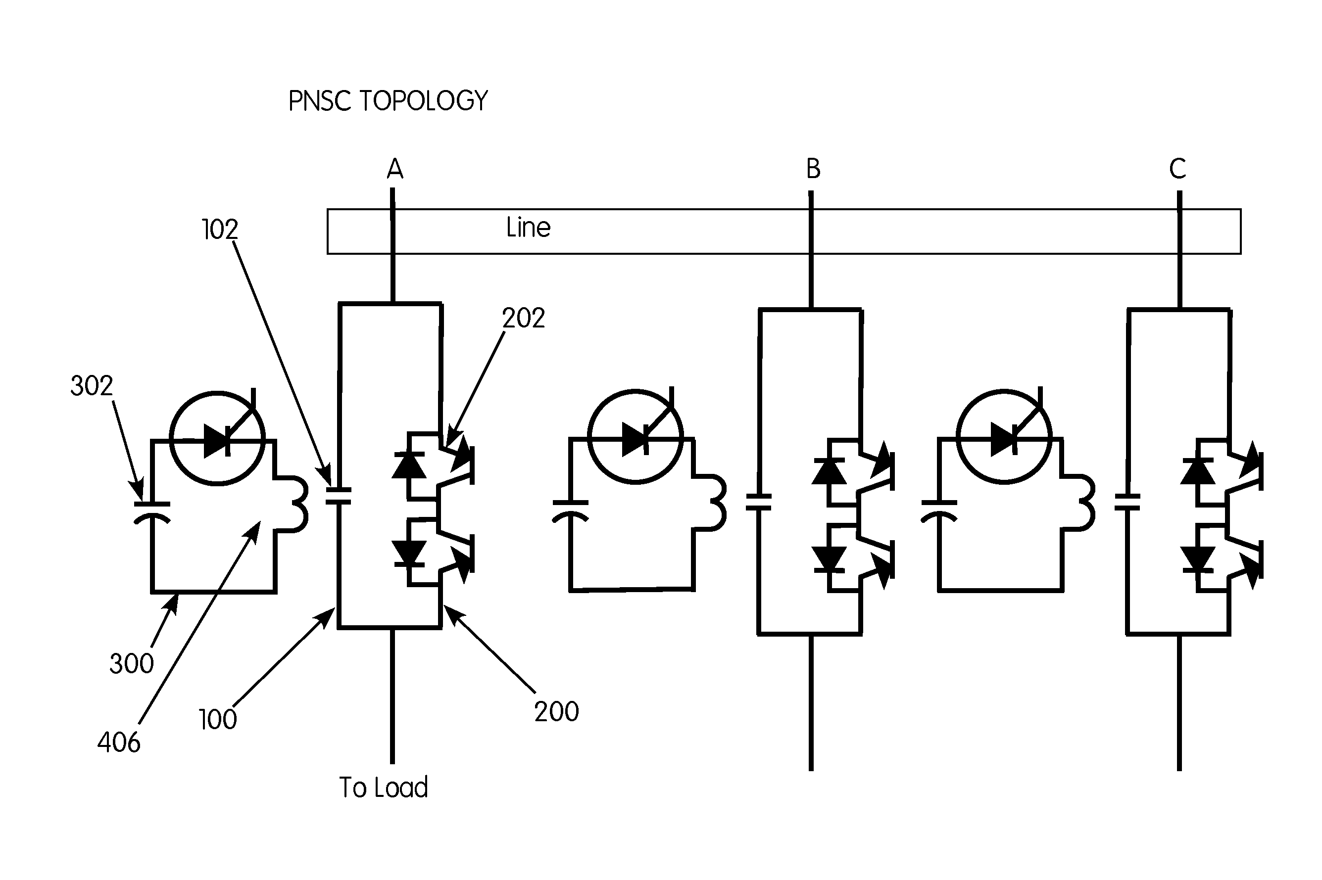
[0039]The operation of the switching module of the power node switching center PNSC consists of three main functions. These are: (1) detection of a fault current; (2) commutation of the current from a path traversing a mechanical contactor to a path through a power electronics switch; and (3) interruption of the fault current by opening the power electronics switch.

[0040]The basic topology of the PNSC switching module is shown in FIG. 3. FIG. 3 shows the switching module in three phase configuration, in which separate circuits for all three phases would be housed in a single enclosure. This is not meant to be a limitation of the invention, however, as any number of phases could be housed together and still be within the spirit of the invention.

[0041]The preferred embodiment of the PNSC switching module consists essentially of two parallel current carrying paths 100 and 200 for each phase. Path 100 includes mechanical contactor 102, and is the primary current carrying path during nor...


PUM


Abstract

A circuit fault detector and interrupter which consists of parallel current conduction paths, including a path through a mechanical contactor and a path through a power electronics switch having active feedback control. A fault can be detected by a fault detection circuit within 50 μS of the occurrence of the fault, causing the mechanical contactor to be opened and the fault current to be commutated via a laminated, low-inductance bus through the power electronics switch. The power electronics switch is thereafter turned off as soon as possible, interrupting the fault current and absorbing the inductive energy in the circuit. The fault current can be interrupted within 200 microseconds of the occurrence of the fault, and the device reduces or eliminates arcing when the mechanical contactor is opened.

Description

RELATED APPLICATION[0001]This application is a continuation-in-part of and claims priority to co-pending U.S. application Ser. No. 12 / 652,383, filed Jan. 5, 2010 and entitled “Power Node Switching Center With Active Feedback Control of Power Switches”, which is a continuation-in-part of U.S. application Ser. No. 11 / 959,055, filed Dec. 18, 2007 entitled “Power Node Switching Center,” now U.S. Pat. No. 7,667,938.BACKGROUND OF THE INVENTION[0002]An electrical power delivery system is a complex system consisting of one or more generators with power flowing through cables to nodes, and then to loads. The functions required of the high-powered nodes are distribution, switching and power management. The functions of conversion and power conditioning are most appropriately handled at the branch level nodes. The node level functions are performed at high-power nodes in prior art legacy systems by circuit breakers and switch gear.[0003]In the event of a fault, a prior art system may permit a ...

Claims


Application Information

Patent Timeline
Patent Type & Authority Applications(United States)
IPC IPC(8): H02H3/033
CPCH01H9/547H01H2009/544H01H2003/225H01H33/285
Inventor LAWLER, ROBERTBARBER, JOHN P.YKEMA, JOHN I.
Owner SPD ELECTRICAL SYST
Why Eureka
Try Eureka