
Method and system for forming composite geometric support structures

a technology of geometric support structure and composite material, which is applied in the direction of girders, manufacturing tools, weaving, etc., can solve the problems of difficulty in the manufacturing method used to form individual support members

Inactive Publication Date: 2013-05-21
SIGMATEK KANSAS
View PDF61 Cites 26 Cited by
  • Summary
  • Abstract
  • Description
  • Claims
  • Application Information

AI Technical Summary

Benefits of technology

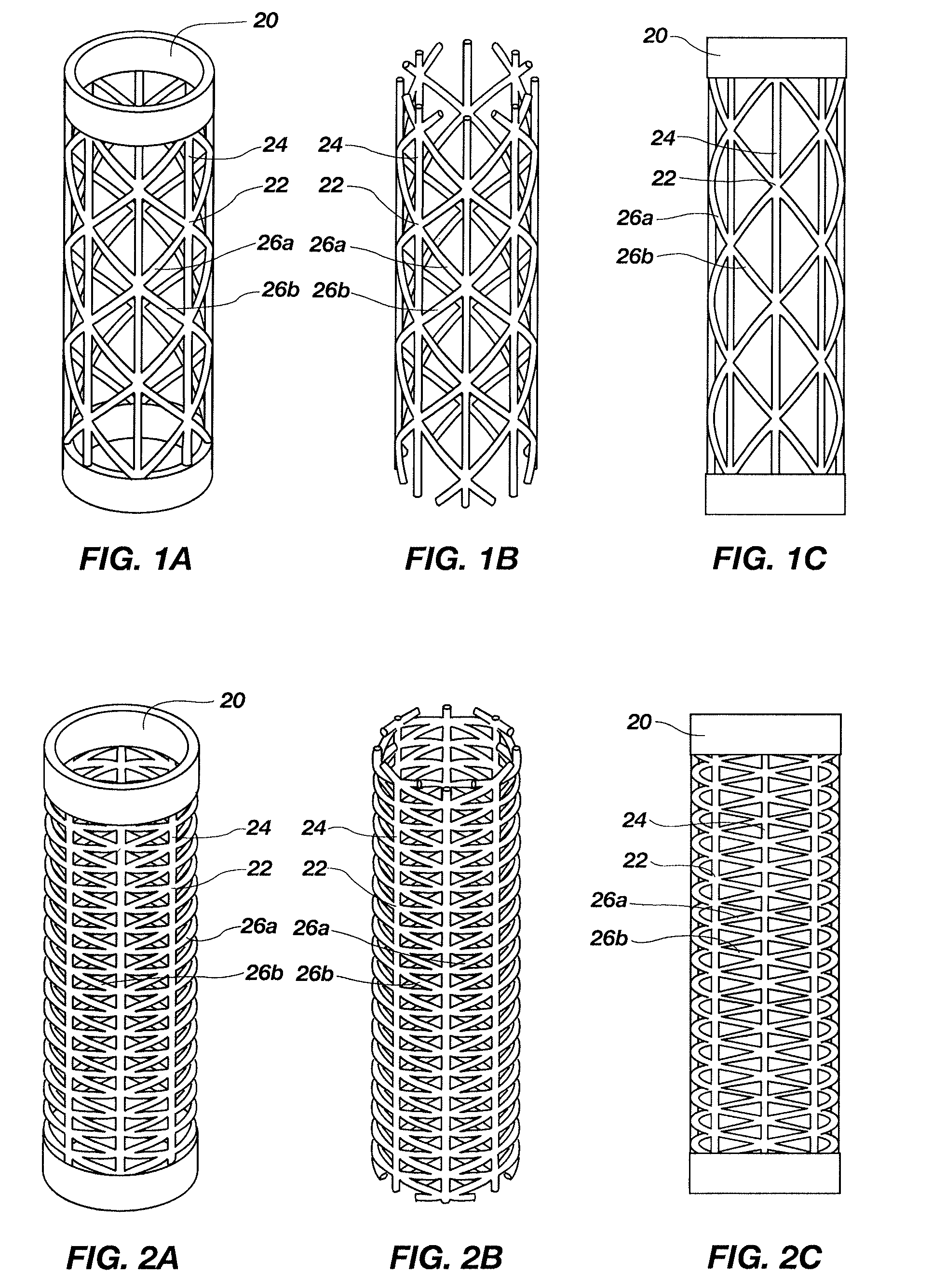
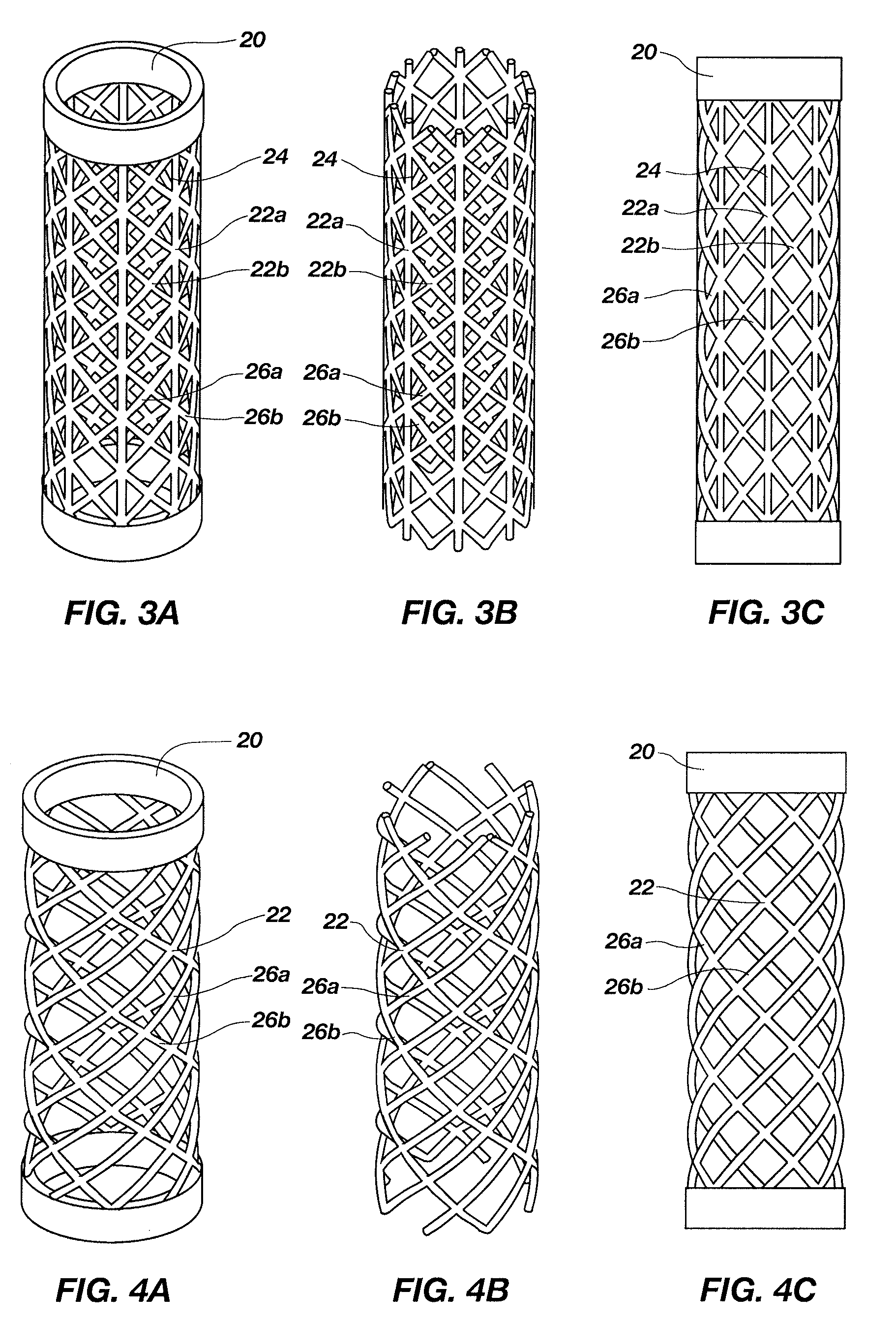
The present invention is about improving the manufacturing process of complex three-dimensional geometric lattice support structures, which are made up of individual support members that need to be joined together. The invention aims to make these structures stronger and lighter than previous methods. The patent describes various methods and systems for forming these support structures, including the use of composite materials and different geometries for the cross supports. The technical effects of the invention include improved load bearing capacity per unit weight and reduced manufacturing costs.

Problems solved by technology

In the field of composite lattice support structures, a primary issue concerning such structures relates to the difficulty in the manufacturing methods used to form the individual support members making up the lattice structure.

Method used


Image

  • Method and system for forming composite geometric support structures
  • Method and system for forming composite geometric support structures
  • Method and system for forming composite geometric support structures

Examples


Embodiment Construction

[0025]The following detailed description of exemplary embodiments of the invention makes reference to the accompanying drawings, which form a part hereof and in which are shown, by way of illustration, exemplary embodiments in which the invention may be practiced. While these exemplary embodiments are described in sufficient detail to enable those skilled in the art to practice the invention, it should be understood that other embodiments may be realized and that various changes to the invention may be made without departing from the spirit and scope of the present invention. Thus, the following more detailed description of the embodiments of the present invention is not intended to limit the scope of the invention, as claimed, but is presented for purposes of illustration only to describe the features and characteristics of the present invention, and to sufficiently enable one skilled in the art to practice the invention. Accordingly, the scope of the present invention is to be def...


PUM

PropertyMeasurementUnit
pressureaaaaaaaaaa
temperatureaaaaaaaaaa
elongationaaaaaaaaaa

Abstract

A method and system for fabricating a geometrically versatile composite lattice support structure having a seamless three-dimensional configuration. The lattice support structure is created by forming two or more cross supports, such as helical, longitudinal, circumferential and / or lateral cross supports, which intersect to form a plurality of multi-layered nodes. The lattice support structure may be designed without any protrusions extending outward from the overall geometry, thus enabling efficient tooling, and thus enabling ease of mass production. The lattice support structure may comprise a completely circumferentially closed geometry, such as a cylinder, ellipse, airfoil, etc. The method for fabricating the lattice support structure comprises laying up a fiber material, in the presence of resin, within rigid channels of a rigid mold, thus creating a green, uncured three-dimensional geometry of unconsolidated cross supports and multi-layered nodes where these intersect. Subjecting these to a curing system functions to consolidate the cross supports and multi-layered nodes to produce the composite lattice support structure.

Description

RELATED APPLICATIONS[0001]This application claims the benefit of U.S. Provisional Application No. 61 / 089,124, filed Aug. 15, 2008, and entitled, “Three-Dimensional Geo-Strut Structure and Method of Manufacture,” which is incorporated by reference in its entirety herein.FIELD OF THE INVENTION[0002]The present invention relates generally to complex three-dimensional geometric lattice support structures that have enhanced load bearing capacity per unit weight, and that are formed from composite materials (e.g., lattice structures formed from carbon or other fiber reinforcements and resin (e.g., polymer matrix) constituents). More particularly, the present invention relates to the methods and systems used in the formation of such structures.BACKGROUND OF THE INVENTION AND RELATED ART[0003]Development of improved support structures in the fields of civil, mechanical and aerospace design is a constant and ongoing effort. One primary focus of these efforts is in producing efficient support...

Claims


Application Information

Patent Timeline
Patent Type & Authority Patents(United States)
IPC IPC(8): B29C70/44
CPCB29C33/42B29C53/821B29C70/342B32B1/08E04B1/19B32B5/12B32B5/26B32B37/1018B32B3/28E04C3/28B29C53/587Y10T428/24124Y10T428/24636Y10T428/1314Y10T428/1362Y10T428/13B29C33/485B29C70/205Y10T442/10
Inventor WILSON, ERICH A.KIPP, MICHAEL D.RIDGES, MICHAEL D.
Owner SIGMATEK KANSAS
Learn More