Electrical junction box

a technology of electrical junction box and distal screw, which is applied in the direction of electrical apparatus casing/cabinet/drawer, gaseous cathode, coupling device connection, etc., can solve the problems of not always being able to obtain sufficient fixing strength, disconnection of arm section from vehicle body panel, etc., to facilitate the attaching work, easy to insert distal screw, and easy to insert arm section

Inactive Publication Date: 2013-05-28
SUMITOMO WIRING SYST LTD
View PDF7 Cites 0 Cited by
  • Summary
  • Abstract
  • Description
  • Claims
  • Application Information

AI Technical Summary

Benefits of technology

[0005]In view of the above problems, embodiments provide an electrical junction box having a new structure that can restrain noises from leaking through a support member and can advantageously secure a fixing strength onto the support member in the electrical junction box fixed on a support member by inserting an arm section projecting from a box main body into an attaching aperture in the support member.

Problems solved by technology

However, since the arm section is inserted into the attaching aperture in the electrical junction box disclosed in Patent Document 1, a clearance is caused between the arm section and the attaching aperture when the electrical junction box is attached to the vehicle body panel.
If only a pair of projections extending outward from the arm section clamp the vehicle body panel to secure the electrical junction box to the vehicle body panel, it is not always possible to obtain a sufficient fixing strength.
There will be a possibility that the arm section will be disconnected from the vehicle body panel on account of vibrations during moving.
That is, according to embodiments, since the arm section is provided with the first wall portion, it is possible to easily insert the arm section into the attaching aperture by providing the sharp portion on the arm section, although the first wall section will be an obstacle for viewing the attaching aperture.

Method used


Image

  • Electrical junction box
  • Electrical junction box
  • Electrical junction box

Examples


first embodiment

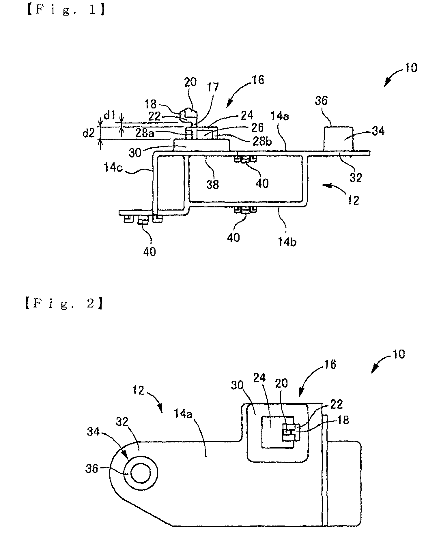
[0024]FIG. 1 shows a top plan view of an electrical junction box 10. FIG. 2 shows a side elevation view of the electrical junction box 10. The electrical junction box 10 is a connector holder. The electrical junction box 10 is a molded product made of nonconductive synthetic resin. The electrical junction box 10 is provided with a substantially parallelepiped box main body 12 that is open at both sides.

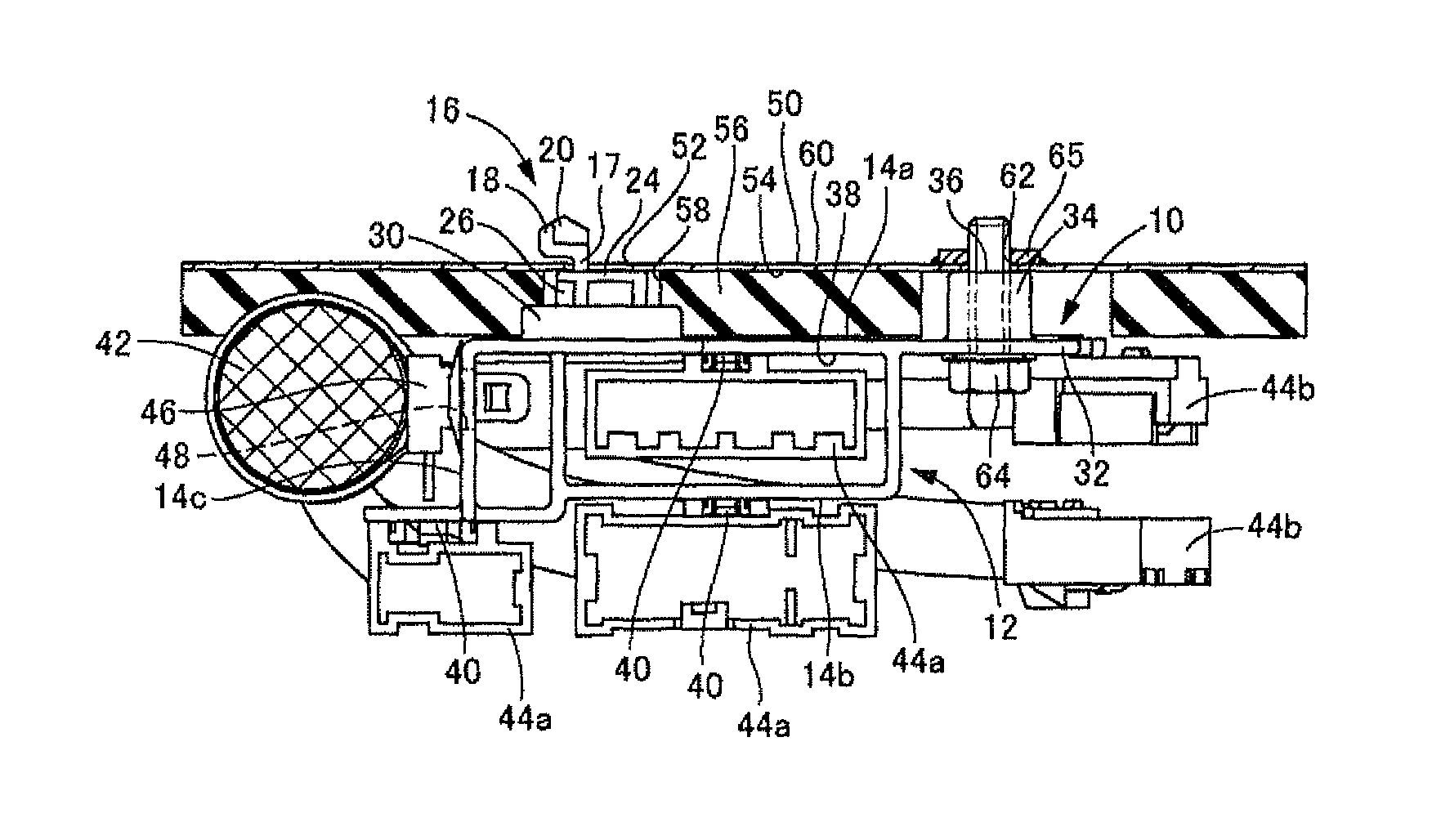
[0025]An arm section 16 projects from a side surface 14a of the box main body 12 opposed to a vehicle body panel 50. The arm section 16 projects from an end of the box main body 12 in a longitudinal direction (a right and left direction in FIG. 1). The arm section 16 is provided with an extension 17 that extends orthogonally from the side surface 14a. The extension 17 is provided on its projecting distal end with a engaging portion 18 that projects orthogonally in an extending direction (an upward direction in FIG. 1) and projects outward in parallel to the side surface 14a in the lon...

third embodiment

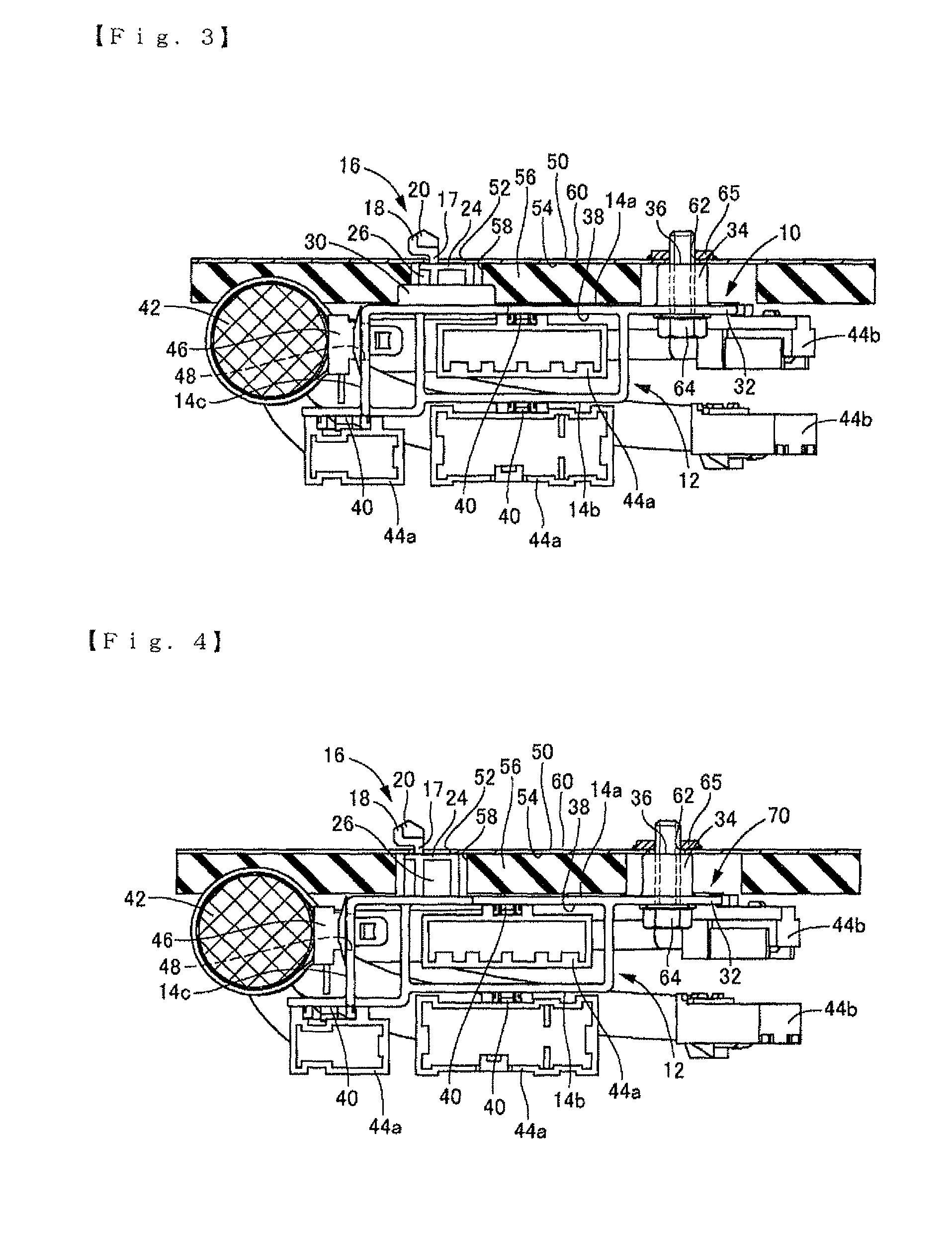
[0045]In the electrical junction box, when the arm section 16 is inserted into the attaching aperture 52, an outer peripheral edge around the first wall portion 72 is pushed to the vehicle body panel 50 in the inserting direction of the arm section 16 (upward direction in FIG. 5) to be elastically deformed. The engaging portion 18 is engaged with the rear surface 60 of the vehicle body panel 50 while the first wall portion keeps its elastic deformation. Thus, since the first wall portion 72 departs from the vehicle body panel 50 by resilience of the first wall portion 72, the engaging portion 18 can be pushed onto the rear surface 60.

[0046]According to the third embodiment, since the first wall portion 72 is formed into a elastically deformable shape, it is possible to press the engaging portion 18 onto the rear surface 60 of the vehicle body panel 50 by artfully utilizing the resilience exerted in the first wall portion 72. Thus, it is possible to obtain a strong fixing force. Sinc...


PUM


Abstract

An object of the present invention is to provide an electrical junction box having a new structure that can restrain noises from leaking through a support member and can advantageously secure a fixing strength onto the support member in the electrical junction box fixed on a support member by inserting an arm section projecting from a box main body into an attaching aperture in the support member. An arm section is loosely inserted into a support member. The arm section is provided on its extending distal end with an engaging portion that is pushed through an attaching aperture in the support member into an interior of the support member to be engaged with a rear surface of the support member. The arm section is integrally provided with a first wall portion opposed through the support member to the engaging portion. The first wall portion covers the attaching aperture.

Description

BACKGROUND[0001]The disclosure relates to an electrical junction box to be mounted on a motor vehicle, and more particularly relates to an electrical junction box to be attached to a support member such as a vehicle body panel or the like.BACKGROUND ART[0002]An electrical junction box such as a fuse box, a junction box, or a connector holder has been used in an electrical equipment system for a motor vehicle. The electrical junction box is attached to a support member such as a vehicle body panel by a bolt or the like in a vehicle room or an engine room.[0003]An example of the electrical junction box to be mounted on the vehicle body panel has been disclosed in JUM HEI 7 (1995)-42535 A (Patent Document 1). In this electrical junction box, an arm section projects from the vehicle body panel at a single position to be attached to the vehicle body panel. The arm section is inserted into an attaching aperture in the vehicle body panel to be engaged with a rear surface of the vehicle bod...

Claims


Application Information

Patent Timeline
Patent Type & Authority Patents(United States)
IPC IPC(8): H02G3/08
CPCH02G3/081
Inventor ORIHARA, ATSURO
Owner SUMITOMO WIRING SYST LTD
Why Eureka
Try Eureka