
Methods and apparatus for network communications via a transparent security proxy

a network communication and security proxy technology, applied in the field of methods and apparatus for network communication via a transparent security proxy, can solve problems such as identity spoofing, denial of service, and loss of privacy, and achieve the effects of reducing processing costs, reducing encryption overhead, and reducing costs

Active Publication Date: 2013-05-28
CISCO TECH INC
View PDF18 Cites 51 Cited by
  • Summary
  • Abstract
  • Description
  • Claims
  • Application Information

AI Technical Summary

Benefits of technology

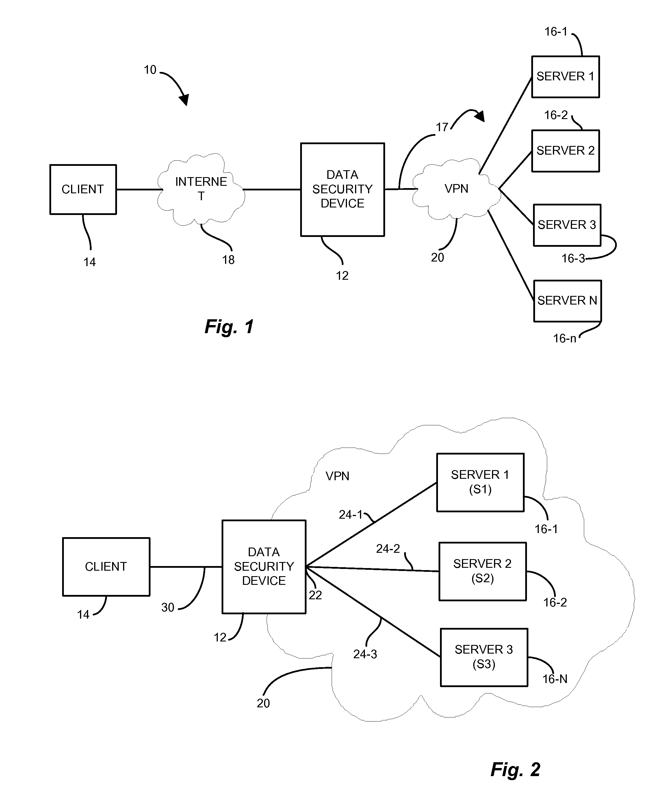
[0012]Further, a server administrator may dispose the servers on a trusted subnetwork or intranet that does not require the level of security that the encryption cipher on the SSL connection from the client mandates. It would be beneficial to implement an arrangement in which the client communicates via an intermediate device acting as a router or gatekeeper, beyond which the transmission employs an alternate security or encryption operation, such that the intermediate device provides a seamless alternative data security medium from the intermediate device to the servers.
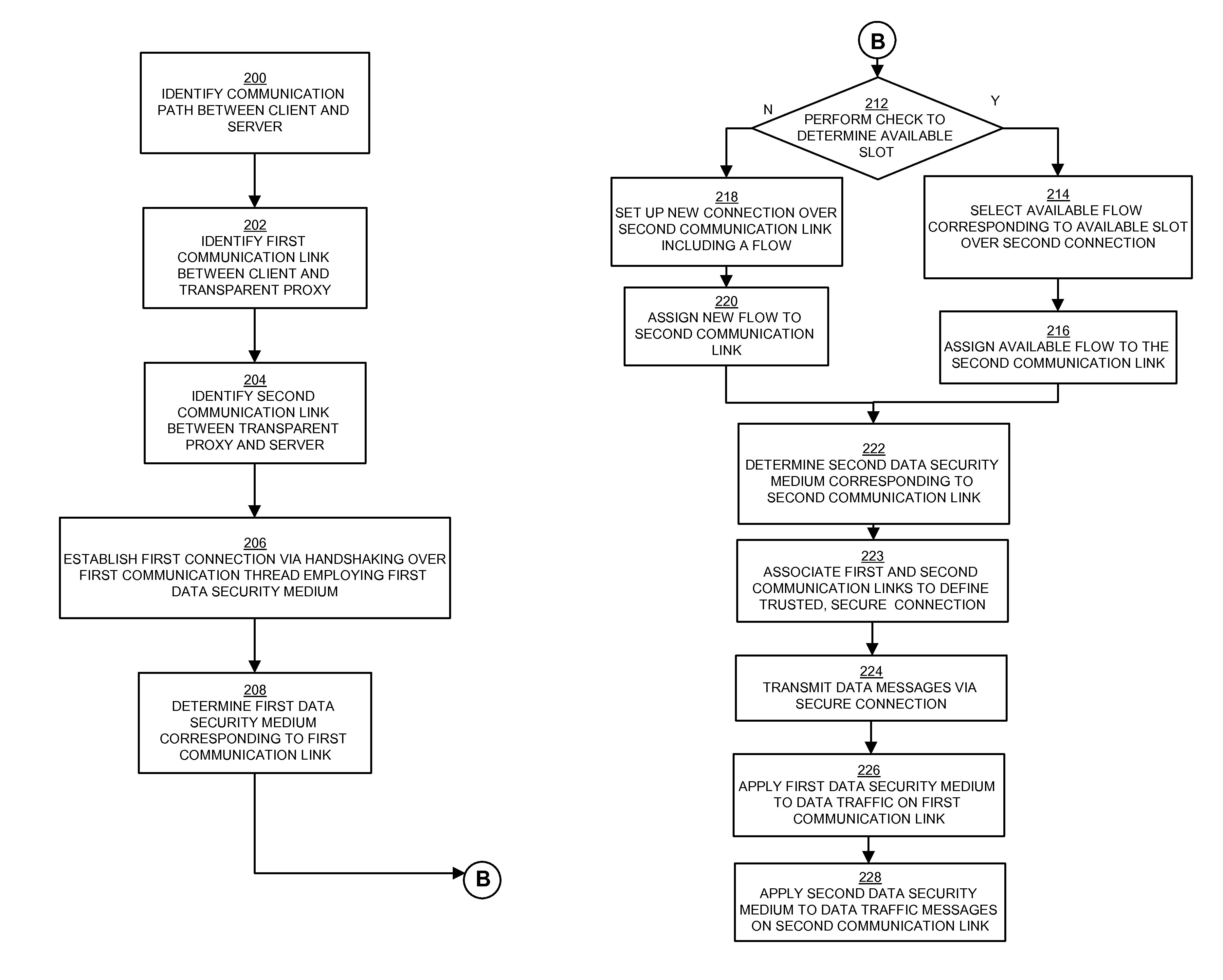
[0016]In one arrangement, a sender node transmits a connection request to establish a secure communication session with an intended receiver node. A transparent proxy process on an intermediate node receives the request, establishes the link employing an encryption mechanism, and issues a positive acknowledgment to the sender node. The transparent proxy establishes a second link with the intended receiver node, and applies a second, less expensive, encryption mechanism that mitigates the encryption overhead. The transparent proxy combines the two links to form the secure connection but incurs only the mitigated processing expense over the second link. Accordingly, the receiver receives the benefit of a secure link over the entire secure connection but relies on the second security medium corresponding to the transparent proxy process to avoid the performance degradation of the first data security medium.
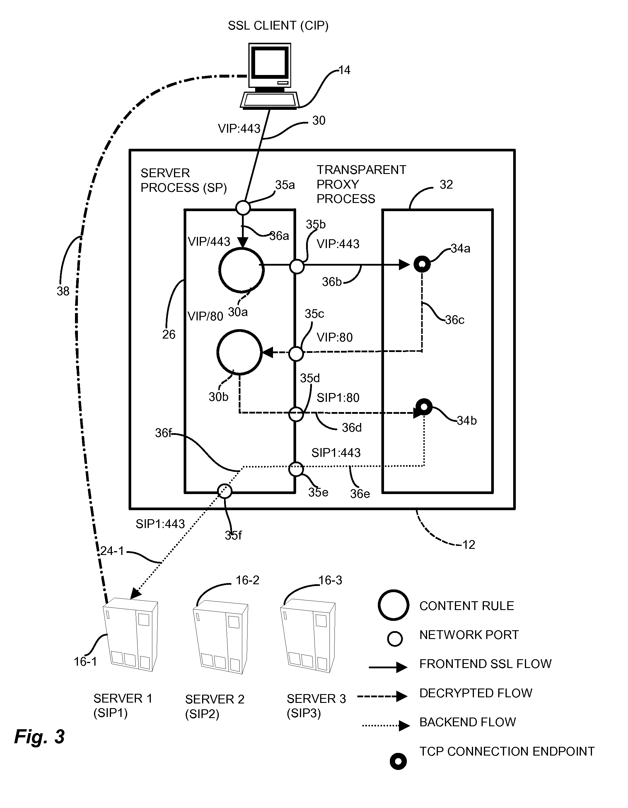
[0017]In a particular arrangement, the combining includes emulating the first node by a transparent proxy such that the second node views data traffic messages sent from the transparent proxy as trusted as data traffic messages sent from the first node. The transparent proxy described above may be provided, for example, by a Cisco CSS (Content Services Switch), marketed commercially by Cisco Systems, Inc., of San Jose, Calif. This arrangement allows the server process expecting the connection to remain unmodified since the incoming connection appears as if it emanated directly from the client.
[0019]In another configuration, the second data security medium further includes indexing a flow entry in a flow table, and determining, based on a matching indexed flow entry, a corresponding flow. The flow table allows session key reuse by subdividing a connection into flows. The transparent proxy then saves and maps the flows for subsequent messages. Therefore, subsequent transmissions reuse connections by mapping to an existing flow and avoid the processing overhead to reestablish the second data security medium.

Problems solved by technology

As the network transmissions travel from the source to the destination, they are subject to a variety of security threats.
Such threats include loss of privacy, loss of data integrity, identity spoofing, and denial of service, to name several.
Other threats are present and known to those skilled in the art.
Such threats may compromise the data traveling through the network in various ways.
Accordingly, an attacker finds it computationally infeasible to intercept and decrypt a message (e.g.“crack the code”) without the key.
However, a user typically employs encryption to represent data in an unintelligible form to protect confidentiality (privacy attack), while a user typically employs authentication to verify integrity, i.e. ensuring sender identity and that the data has not been modified.
Generally, a larger key having a greater number of bits provides stronger security, but also imposes a more computationally intensive encryption operation, therefore reducing throughput due to overhead.
Because of the computationally expensive nature of such encryption operations, the computing resources available are often a limiting factor in the degree of security that the specified encryption medium applies to a given connection while still maintaining required throughput.
However, SSL operations impose throughput constraints because of the computationally intensive nature of the encryption.
Specifically, the SSL handshake requires substantial processing to set up the SSL connection.
Further, conventional approaches delegate SSL termination only, and are not concerned with a mechanism to implement security from the SSL offloader to the intended recipient.
Unfortunately, there are deficiencies with the above-described SSL implementation because the SSL connection is broken at the SSL offloader.
Further, the SSL handshake and encryption overhead still occurs for each sender / receiver pair that establish a connection.
The SSL connection overhead occurs, therefore, for each server engaged by the client, however, does not provide security along the entire path from the client to the server because the SSL connection is broken at the SSL offloader.
As indicated above, the security level (based on the difficulty to “crack” the code) and computational expense increase exponentially with the key size.
Therefore, the client user need only incur the SSL overhead and handshake with respect to the frontend connection, while the backend connection employs a computationally less expensive, albeit adequate, data security medium over the intranet.

Method used


Image

  • Methods and apparatus for network communications via a transparent security proxy
  • Methods and apparatus for network communications via a transparent security proxy
  • Methods and apparatus for network communications via a transparent security proxy

Examples


Embodiment Construction

[0032]The invention is directed to techniques for providing a network transport connection via a transparent network proxy that employs different encryption security mediums along a communications session between two endpoints by emulating one of the endpoints at an intermediate node such that the communication session appears as an atomic, secure connection to the endpoint nodes yet provides appropriate security over the end-to-end connection. A sender node initiates a secure communication session with an intended receiver node. A transparent proxy process on the intermediate node receives the request, establishes the link employing an encryption mechanism, and issues a positive acknowledgment to the sender node. The transparent proxy establishes a second link with the intended receiver node, and applies a second, computationally less expensive, encryption mechanism. The transparent proxy combines the two links to form the secure connection but incurring only the mitigated computat...


PUM


Abstract

A data security device for providing a network transport connection via a transparent network proxy that employs different encryption security mediums along a communications session between two endpoints by emulating one of the endpoints at an intermediate node such that the communication session appears as an atomic, secure connection to the endpoints yet provides appropriate security over the end-to-end connection. A sender node sends a connection request to establish a secure communication session with an intended receiver node. A transparent proxy on an intermediate node receives the request and establishes the link employing an encryption mechanism. The transparent proxy establishes a second link with the intended receiver, and applies a second, less expensive encryption mechanism. The transparent proxy combines the two links to form the trusted, secure connection but incurring only the mitigated expense over the second link.

Description

CROSS REFERENCE TO RELATED APPLICATIONS[0001]This patent application is a Continuation of U.S. patent application Ser. No. 10 / 365,940 filed on Feb. 13, 2003 entitled, “METHODS AND APPARATUS FOR NETWORK COMMUNICATIONS VIA A TRANSPARENT SECURITY PROXY”, now issued as U.S. Pat. No. 7,506,368, the contents and teachings of which are hereby incorporated by reference in their entirety.BACKGROUND OF THE INVENTION[0002]Companies often employ data security techniques with computer networks to maintain privacy and integrity of the data traveling through such networks. Such data travels via a variety of physical paths and transmission mediums from sources to destinations. As the network transmissions travel from the source to the destination, they are subject to a variety of security threats. Such threats include loss of privacy, loss of data integrity, identity spoofing, and denial of service, to name several. Other threats are present and known to those skilled in the art.[0003]Such threats ...

Claims


Application Information

Patent Timeline
Patent Type & Authority Patents(United States)
IPC IPC(8): H04L29/06
CPCH04L63/0428H04L63/0464H04L63/10H04L9/3263H04L2209/56H04L2209/76H04L9/321H04L9/14H04L9/32H04L63/0281H04L63/0471
Inventor KERSEY, EDWARD C.O'TOOLE, JR., JAMES W.DIKE, BRADLEY DALETATE, PATRICK DARRELLFRITZGES, ERIC A.PECQUEUR, ANDRE JUSTINWONG, BRUCE F.PRASAD, HEMA M.BACCHUS, SHAHEEDBISEL, LARRY DAVID
Owner CISCO TECH INC
Learn More