Atherectomy device supported by fluid bearings

a technology of atherectomy and fluid bearings, which is applied in the field of rotational atherectomy devices, can solve the problems of affecting the normal operation affecting the function of the heart muscle, and affecting the function of the heart muscl

Inactive Publication Date: 2013-06-04
CARDIOFLOW
View PDF54 Cites 51 Cited by
  • Summary
  • Abstract
  • Description
  • Claims
  • Application Information

AI Technical Summary

Benefits of technology

The invention is a device for removing a blockage in a vessel of a patient. It consists of a flexible drive shaft with a distal end and a solid support element. The drive shaft has a torque transmitting coil and a fluid impermeable membrane forming a fluid impermeable lumen for fluid to flow through. The device creates a layer of fluid between the solid support element and the wall of the vessel being treated, which acts as a fluid bearing to prevent the formation of a thrombus. The device can be rotated and longitudinally moved within the treated vessel. The technical effect of the invention is to provide a safe and effective device for removing blockages in blood vessels.

Problems solved by technology

However, a disadvantage with this technique is that abraded particles can migrate along the blood vessel distally and block very small diameter vessels including capillaries of the heart muscle itself.
Clearly, the existence of particulate matter in the blood stream is undesirable and can cause potentially life-threatening complications, especially if the particles are over a certain size.
The rotational atherectomy device known from U.S. Pat. No. 5,681,336 (to Clement et al.) has a complicated construction and is difficult to manufacture on a commercial scale.

Method used


Image

  • Atherectomy device supported by fluid bearings
  • Atherectomy device supported by fluid bearings
  • Atherectomy device supported by fluid bearings

Examples


Embodiment Construction

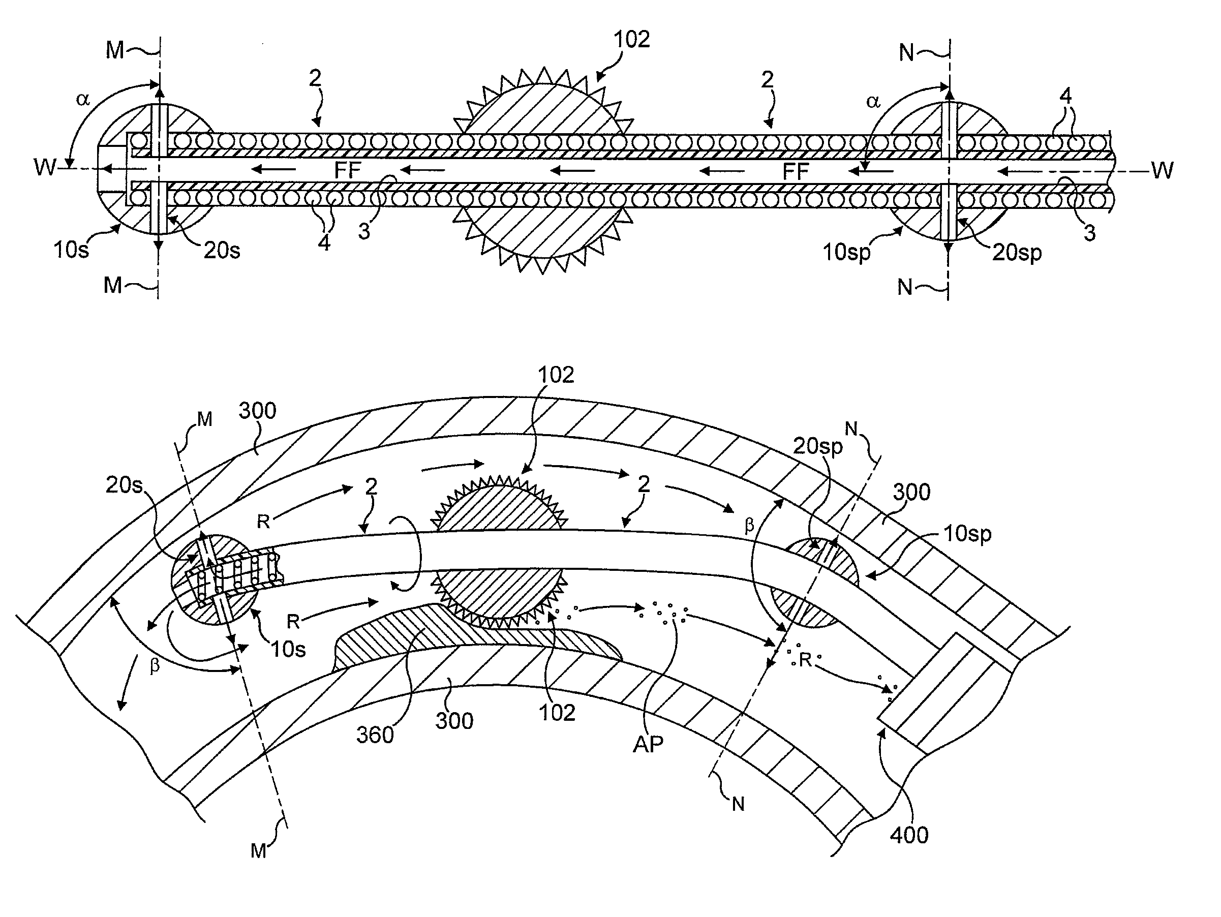
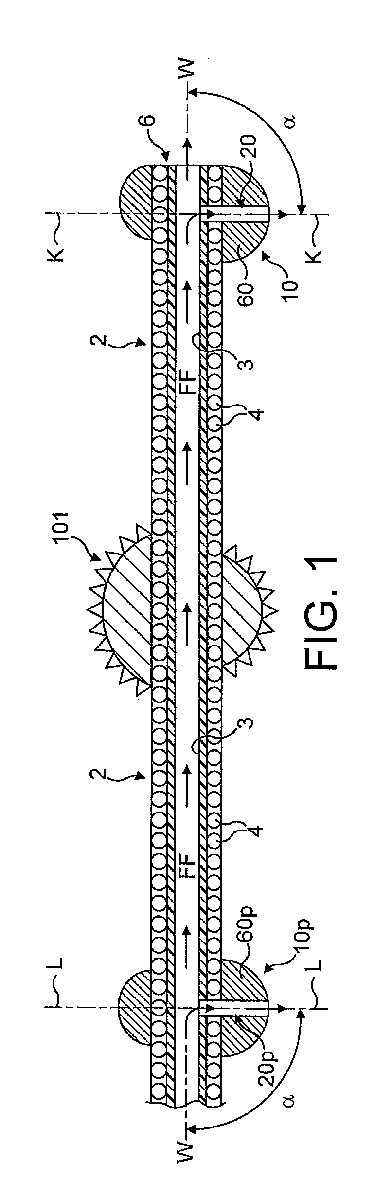
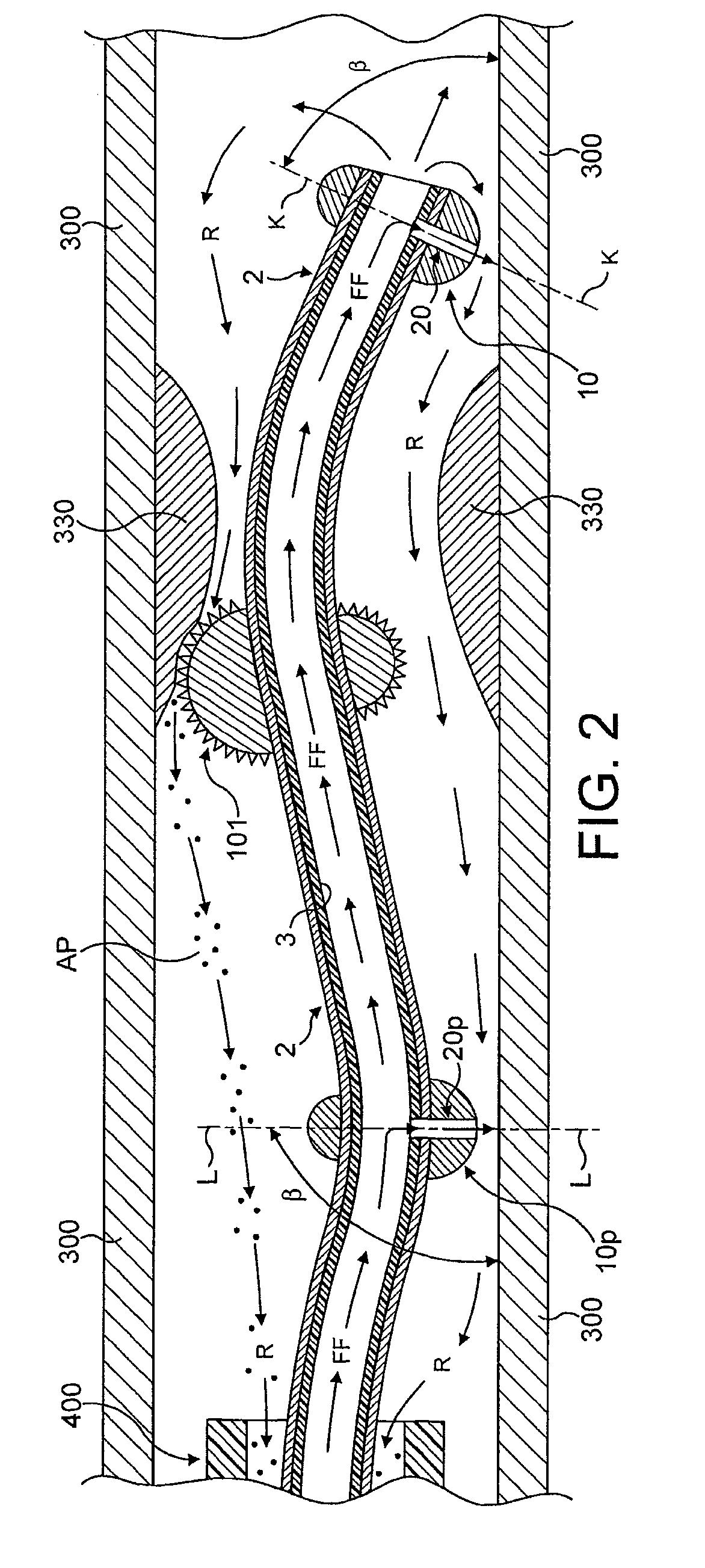
[0028]In FIGS. 1 to 4, the antegrade flow of fluid is indicated by arrows “FF” and the flow of fluid in a retrograde direction is indicated by arrows marked “R”. Abraded particles AP abraded from the stenotic lesion 330 are aspirated into a lumen of a drive shaft sheath 400 so that the retrograde flowing fluid and the abraded particles entrained in said fluid can be removed from the treated vessel and out of the patient's body.

[0029]Referring to the drawings, there is shown a rotational atherectomy device for removing a stenotic lesion from within a vessel of a patient using an abrasive element mounted to a rotatable, flexible, hollow drive shaft formed by a torque transmitting coil and a fluid impermeable membrane. The drive shaft has a longitudinal axis of rotation and is provided with two rounded solid support elements. Each of the two solid support elements is spaced away from the abrasive element and includes at least one outflow channel which is directed radially outward and c...


PUM


Abstract

A rotational atherectomy device for removing a stenotic tissue (330, 360) from a vessel (300) of a patient comprises a flexible hollow drive shaft (2) and an abrasive element (101, 102) mounted to the drive shaft proximal to and spaced from a solid support element (10, 10s) mounted at the distal end (6) of the drive shaft, the solid support element having a rounded outer surface and an outflow channel (20, 20s) with an outflow opening in said rounded outer surface. The drive shaft comprises a torque transmitting coil (4) and at least one fluid impermeable membrane (3) forming a fluid impermeable lumen for the antegrade flow (FF) of fluid into the outflow channel such that, during rotation of the drive shaft, a flow of fluid out of said outflow opening forms a fluid bearing between the rotating solid support element and the wall of the treated vessel.

Description

CROSS-REFERENCE TO RELATED APPLICATIONS[0001]This is a continuation of U.S. patent application Ser. No. 12 / 373,461 filed on Jan. 12, 2009, which is a national phase application based on PCT / EP2007 / 056499 filed on Jun. 28, 2007, which claims priority to GB Patent Application No. 0613979.4 filed on Jul. 13, 2006. The contents of these prior applications are incorporated herein by reference.BACKGROUND[0002]1. Field[0003]The present invention provides a rotational atherectomy device for removing a stenotic lesion from within a vessel of a patient. More specifically, the invention relates to a rotational atherectomy device for removing or reducing stenotic lesions in blood vessels such as a human artery by rotating an abrasive element within the vessel to partially or completely ablate the unwanted material.[0004]2. Description of Related Art[0005]Atherosclerosis, the clogging of arteries, is a leading cause of coronary heart disease. Blood flow through the peripheral arteries (e.g., car...

Claims


Application Information

Patent Timeline
Patent Type & Authority Patents(United States)
IPC IPC(8): A61B17/22
CPCA61B17/320758A61B17/32037
Inventor SHTURMAN, LEONID
Owner CARDIOFLOW
Why Eureka
Try Eureka