Techniques for determining hearing threshold

a technology of hearing threshold and inclination, which is applied in the field of noninvasively determining a hearing threshold, can solve the problems of too much variation in the intensity of corresponding stimulus, too much slope, and too much inaccuracy in determining timing-related parameters, so as to reduce timing-related inaccuracy, accurate estimation of the hearing threshold, and large errors in the hearing threshold.

Active Publication Date: 2013-06-04
PIXART IMAGING INC
View PDF7 Cites 9 Cited by
  • Summary
  • Abstract
  • Description
  • Claims
  • Application Information

AI Technical Summary

Benefits of technology

[0015]In step c), the test subject's brain response to the stimulus is recorded by a non-invasive technique, such as EEG or MEG. The recording should span a time window in which the transient brain response is to be expected, which in practice means the duration of the ramp plus the latency delay and duration of the transient brain response. The idea is to enhance the likelihood of the brain response being caused by the ramp section of the acoustic stimulus. For example, the time window can span the duration of the ramp plus approximately 200 ms for normal adults and 400 ms for infants and certain groups of special test subjects.
[0017]Step e) comprises using the plurality of recorded brain responses and the a-priori information on transient brain response to the acoustic stimulus to determine a combined time interval between the acoustic stimulus and the transient brain response. Use of the a-priori information, such as known representative wave shapes of the P1 and N1 brain waves, improves detection of transient brain responses which may otherwise be buried under EEG noise. The combined time interval means a time interval value which is representative of the plurality of recorded brain responses. By way of a non-restrictive example, such a representative value may be obtained by time-aligning the recorded brain responses in relation to the acoustic stimulus. The time-aligned responses are then combined in a combinatory process which emphasizes a relative proportion of the transient response. Simple implementations of such a combinatory process include summing, averaging and multiplication. In more complex implementations of the combinatory process, the times of the brain response, relative to the stimulus, are only starting values, and the times of individual brain responses may be fine-tuned within some predetermined margin around the starting values, such that maximum correlation between the recorded brain responses is reached in a time window in which the transient brain response is expected. The representative value of the time interval between the acoustic stimulus and the transient brain response may be expressed as a single scalar value or as a distribution of values, for example.
[0021]A benefit of the invention is improved ability to detect transient brain responses to ramp stimuli even when conventional techniques for time-aligning trials fail to provide useful responses. These signals may be examined with special single-trial techniques, and the detected responses are used in determining hearing threshold.
[0027]Applying short ramps to hearing threshold determination requires accurate determination of the combined time interval between the acoustic stimulus and the transient brain responses. This is because in a short ramp stimulus, the sound pressure level increases steeply, and any inaccuracies in timing of the transient brain response cause large errors in the hearing threshold. On the other hand, use of short ramps may reduce timing-related inaccuracies, firstly, because short ramps yield transient brain responses which have more clearly defined morphology, and, secondly, through the use of reference information. One reason for the use of reference information is that the combined time interval between sound onset and the transient brain varies also using steady state (short onset) stimuli due to factors like inter-individual differences, alertness of the subject, and the frequency of stimulation. Therefore also with ramped stimuli the combined time interval between sound onset and the transient brain depends not only on the hearing threshold but also on other factors. Using a steady state reference stimulus with an intensity clearly exceeding the hearing threshold, the contribution of the factors such as inter-individual differences and stimulus frequency on the combined time interval can be estimated. Then this reference information can be used to obtain a more accurate estimate of the hearing threshold with the ramped stimuli.
[0028]The reference information can be obtained, for example, by recording the brain responses for the same frequency stimuli as the ramped stimuli but with short onsets. Such an acoustic reference stimulus may be, for example, a sound used separately for obtaining the reference information for the transient response. Alternatively, it can be incorporated to a stimulus which has the ramp section used for determination of hearing threshold but which also has separate portion that elicits a separate transient response which is used to obtain the reference information. Furthermore, variables such as the alertness of the test subject can be maintained the same to those that are present with the ramped stimuli by presenting the acoustic reference stimuli randomly within the same sequence as the ramped stimuli. The reference information may also be obtained from an offset response elicited by the ending of acoustic stimuli.

Problems solved by technology

If the slope is too steep (the intensity increases by too many decibels per unit of time), any variation in timing-related measurements, such as latency, causes too much variation in the corresponding stimulus intensity.
Also, the inherent inaccuracy of the human auditory system may cause problems in determining timing-related parameters, such as latency.
On the other hand, making the stimulus slope too gentle broadens the time window in which the transient response is to be detected.
On the other hand ramp durations above 5 second consume excessive time and introduce problems into the detection of the transient response.

Method used


Image

  • Techniques for determining hearing threshold
  • Techniques for determining hearing threshold
  • Techniques for determining hearing threshold

Examples


Embodiment Construction

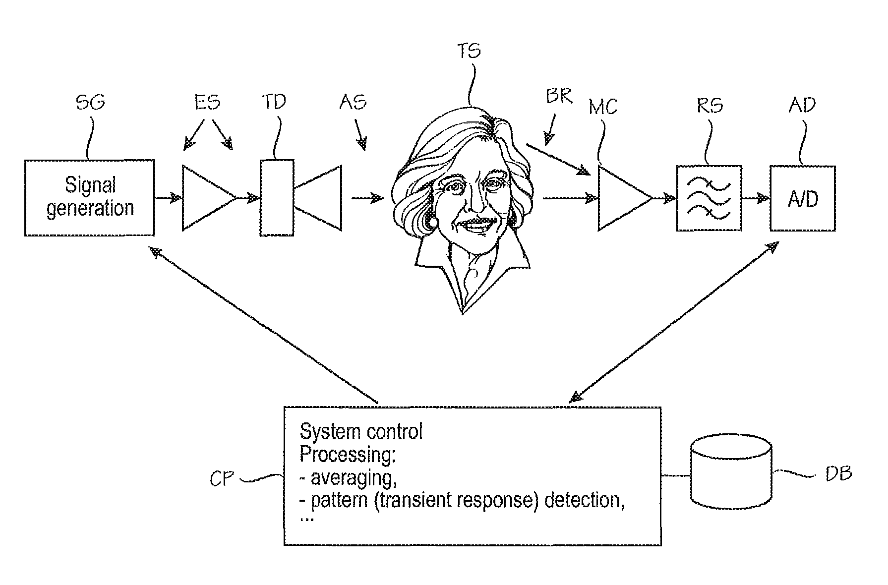
[0034]Specific embodiments of the invention will be described. Most of the description is based on the assumption that the measured brain response is EEG response. An MEG response could be measured equally well, but MEG equipment is more expensive than EEG equipment.

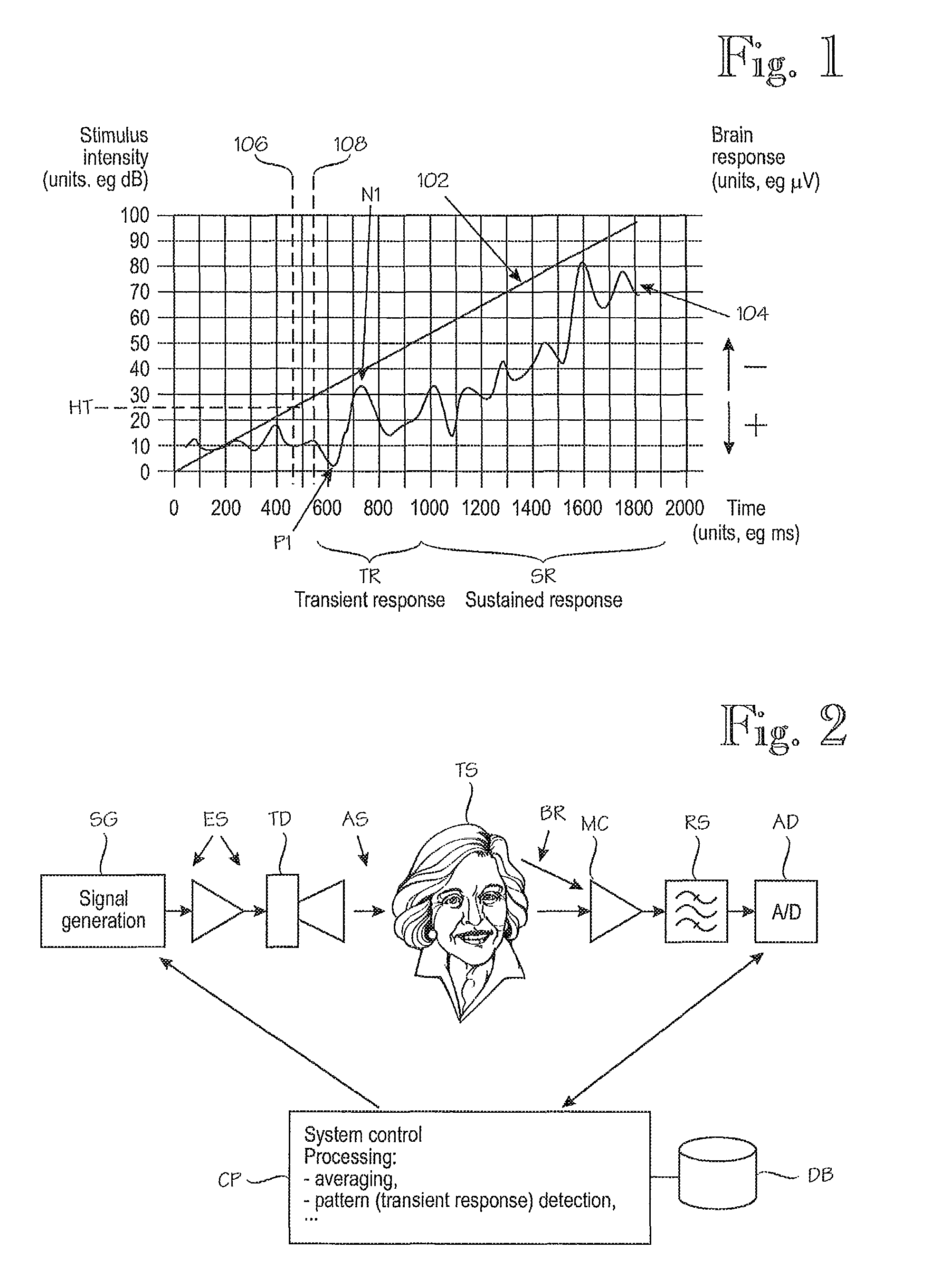
[0035]FIG. 1 shows some key concepts relating to the invention. Reference numeral 102 denotes an acoustic stimulus. Considering the logarithmic nature of human hearing, a preferred form of the acoustic stimulus 102 contains a rising ramp in which the slope expressed in decibels per unit of time is constant or at least approximately constant. Alternatively, the ramp could be created in another suitable domains applying compression functions such as cubic root which approximates hearing even better than logarithmic function. Reference numeral 104 denotes the test subject's brain response, which in this particular example is an EEG response. It is customary to present EEG graphs such that positive voltage fluctuations are t...


PUM


Abstract

A computerized method for determining a test subject's (TS) hearing threshold (HT). An acoustic stimulus (AS, 102) is applied the test subject's (TS) ear. The stimulus intensity is increased during a ramp, with a predetermined dependency on time, such that the intensity begins below the hearing threshold and ends above it. The test subject's brain response (104), which includes a transient brain response (TR)1 is non-invasively recorded during the ramp section. The stimulus-response cycle is repeated several times. The recorded brain responses and stored a-priori information on transient brain response to the acoustic stimulus are used to determine a combined time interval between the acoustic stimulus and the transient brain response. The test subject's hearing threshold is determined based on the predetermined dependency on time of the intensity during the ramp and the combined time interval between the acoustic stimulus and the transient brain response.

Description

PARENT CASE INFORMATION[0001]This application is the National Phase of PCT / FI2007 / 050597 filed on Nov. 8, 2007, which claims priority under 35 U.S.C. 119(e) to U.S. Provisional Application No. 60 / 925,994 filed on Apr. 24, 2007 and under 35 U.S.C. 119(a) to Patent Application No. 20065759 filed in Finland on Nov. 29, 2006, all of which are hereby expressly incorporated by reference into the present application.BACKGROUND OF THE INVENTION[0002]The invention relates to methods, equipment and software products for non-invasively determining a hearing threshold of a test subject, by recording one or more brain responses to one or more acoustic stimuli. Non-restrictive examples of the brain responses include electroencephalography (EEG) responses and magnetoencephalography (MEG) responses, commonly referred to as “brainwaves”. The invention can be used in diagnostic and non-diagnostic applications.[0003]A general problem in techniques which involve recording brainwave responses to an acou...

Claims


Application Information

Patent Timeline
Patent Type & Authority Patents(United States)
IPC IPC(8): A61B5/04
CPCA61B5/121A61B5/04845A61B5/38
Inventor MAKINEN, VILLE
Owner PIXART IMAGING INC
Why Eureka
Try Eureka