Method and device for operating a hybrid vehicle

a hybrid vehicle and hybrid technology, applied in hybrid vehicles, process and machine control, instruments, etc., can solve the problems of rotational vibration, inability to precisely determine inability to accurately compensate the starting torque or starting power, so as to prevent the resulting temporary dip in angular velocity

Active Publication Date: 2013-06-04
ROBERT BOSCH GMBH
View PDF22 Cites 2 Cited by
  • Summary
  • Abstract
  • Description
  • Claims
  • Application Information

AI Technical Summary

Benefits of technology

[0007]The method according to the present invention for operating a hybrid vehicle has the advantage that during the start and / or stop of the first drive unit, the torque or power of the second drive unit is acted upon based on a measured, observed or modeled characteristic of the longitudinal movement of the hybrid vehicle in order to counteract the disturbance occurring when starting and / or stopping the first drive unit. At the start of the first drive unit, the first drive unit is tow-started, thereby preventing a resulting temporary dip in the angular velocity of the second drive unit. Likewise, a temporary increase in the angular velocity of the second drive unit is compensated; this may occur in ramp-up of the first drive unit due to overshooting of the angular velocity of the first drive unit.
[0009]Advantageously at least one of the variables derived from the longitudinal movement of the hybrid vehicle is a setpoint value, which is compared with an actual value supplied by the second drive unit and / or from the movement of the hybrid vehicle, the torque or the power of the second drive unit being regulated as a function of the comparison. In this way, a control loop over the entire drive train is closed. Units or transfer elements of the drive train having only imprecisely known properties, for example, a torque converter or a converter clutch, are inside the control loop. Their values, which influence the drive train, are detected by regulation feedback. Since inaccuracies are compensated by regulation, high driving comfort is made possible and rotational vibrations are regulated out optimally.
[0010]In one embodiment, the variable derived from the longitudinal movement of the hybrid vehicle is determined by measuring the wheel rotational speeds, the wheel rotational accelerations, the longitudinal speed of the vehicle and / or the longitudinal acceleration of the vehicle. Using these measurements and calculations, which are determined as such for other applications in the hybrid vehicle, it is possible to determine the desired parameter inexpensively. Additional use of sensors or an increase in the computing capacity of microcomputers in the vehicle is not necessary.
[0019]It is favorable if the modeled longitudinal movement of the vehicle and the setpoint values determined therefrom do not include any vibrating components. Regulation then includes a vibration damping effect.
[0021]In another further refinement, in the case of a device for operating a hybrid vehicle, an idle first drive unit is started by transferring a torque from an operating second drive unit to the first drive unit. To minimize effects during starting and / or stopping of the first drive unit on the movement characteristics of the hybrid vehicle, means are present for influencing the torque or the power of the operating second drive unit through a variable derived from the longitudinal movement of the hybrid vehicle. This achieves a high level of driving comfort of the hybrid vehicle because effects of vibration on the vehicle mass in particular are suppressed.
[0024]In one further refinement, the first drive unit is situated on a first vehicle axle and the second drive unit is situated on a second vehicle axle. Alternatively, the first drive unit may act on one wheel of the motor vehicle, while the second drive unit acts on another wheel. For example, tow-start and acceleration of the first drive unit may be accomplished by the second drive unit via a friction-locking effect over the road. The control loop is then closed for the entire vehicle. Inaccuracies are compensated and driving comfort is improved.

Problems solved by technology

In addition, the required time characteristic of the starting torque or the starting power is not precisely determinable due to varying friction and compression conditions of the internal combustion engine.
Both prevent accurate compensation of the starting torque or the starting power by the electric motor or the hydraulic motor.
The uncompensated portion acts as a disturbance on the drive train that causes rotational vibrations and reduces driving comfort.

Method used


Image

  • Method and device for operating a hybrid vehicle
  • Method and device for operating a hybrid vehicle
  • Method and device for operating a hybrid vehicle

Examples


Embodiment Construction

[0031]The same features are indicated by the same reference numerals in the figures.

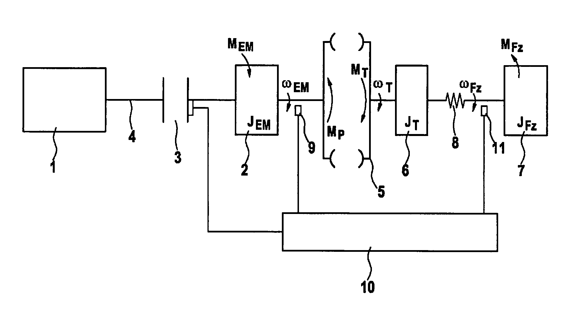
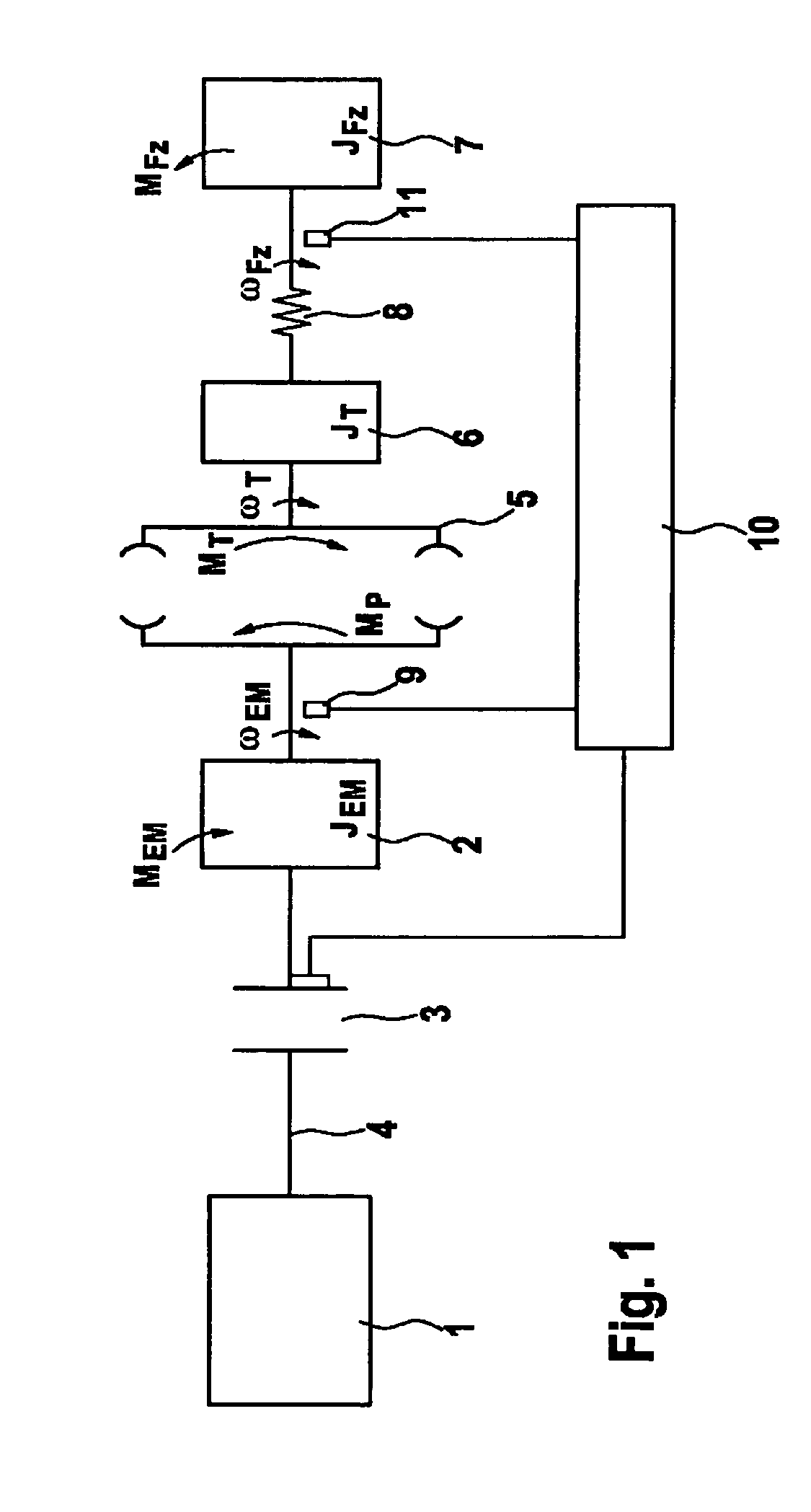
[0032]FIG. 1 shows a simplified model of a parallel hybrid drive train, in which an internal combustion engine 1 and an electric motor 2 are connected to one another via a separating clutch 3. Electric motor 2 is positioned on drive shaft 4 of internal combustion engine 1. Electric motor 2 drives the drive wheels (not shown here) of the vehicle via a torque converter 5 and an automatic transmission (also not shown here).

[0033]The rotatory moments of inertia of the turbine rotating at angular velocity ωT of torque converter 5 and of parts of the automatic transmission are translated to the transmission input shaft and combined with moment of inertia JT, which is associated with torque converter 5, in a rotatory turbine rotational mass 6.

[0034]The rotatory inertias of drive shafts and wheels as well as the translationally moving vehicle mass (representing the inertia of the vehicle) are translated to t...


PUM


Abstract

In a method for operating a hybrid vehicle, an idle first drive unit is started during the driving of the hybrid vehicle by transferring part of a torque from an operating second drive unit to the first drive unit. To minimize effects on the movement characteristics of the hybrid vehicle during starting and / or stopping of the first drive unit, a control unit is provided for influencing the torque of the operating second drive unit by at least one of the variables derived from the longitudinal movement of the hybrid vehicle.

Description

BACKGROUND OF THE INVENTION[0001]1. Field of the Invention[0002]The present invention relates to a method for operating a hybrid vehicle, in which an idle first drive unit is started while the hybrid vehicle is being driven, by transferring a torque from an operating second drive unit to the first drive unit, and a device for implementing this method.[0003]2. Description of Related Art[0004]Vehicles having a hybrid drive structure usually have an internal combustion engine as the first drive unit and an electric motor or a hydraulic motor as the second drive unit. Other additional drive units are also possible. For example, the torque may be applied by the drive units during the starting operation of the hybrid vehicle. All-electric or hydraulic driving is also possible. It may be necessary to start the internal combustion engine during electric or hydraulic driving, for example, if the driver requires more power than the electric motor or the hydraulic motor is able to supply or if...

Claims


Application Information

Patent Timeline
Patent Type & Authority Patents(United States)
IPC IPC(8): B60L9/00B60L11/00G05D1/00G05D3/00G06F7/00G06F17/00
CPCB60W10/08B60W30/18072B60W30/192B60W10/06B60L2240/423Y10T477/23B60W20/00B60W2520/10B60W2520/105B60W2520/28B60W2710/083Y02T10/6286Y02T10/642B60W2050/0041Y02T10/56Y10T477/75Y02T10/40Y02T10/64Y02T10/62B60K2006/268B60W2510/24
Inventor FALKENSTEIN, JENS-WERNER
Owner ROBERT BOSCH GMBH
Why Eureka
Try Eureka