Injection method for inert gas

a technology of inert gas and injection method, which is applied in the direction of charge manipulation, combustion types, furnaces, etc., can solve the problems of ineffective internal shroud method for producing coherent jets of inert gases, oxidation of steel and undesirable by-products, and affecting the quality of steel, so as to reduce the supply pressure, enhance the beneficial stirring action of the melt, and reduce the effect of the stirring action

Active Publication Date: 2011-06-14
PRAXAIR TECH INC
View PDF36 Cites 3 Cited by
  • Summary
  • Abstract
  • Description
  • Claims
  • Application Information

AI Technical Summary

Benefits of technology

[0017]Ignition and combustion of the fuel while within the passageway is prevented by not introducing an ignition source and providing the passageway with an inner surface uninterrupted by any discontinuity within which the outer circumferential region could otherwise decelerate and provide a site for stable combustion of the fuel.
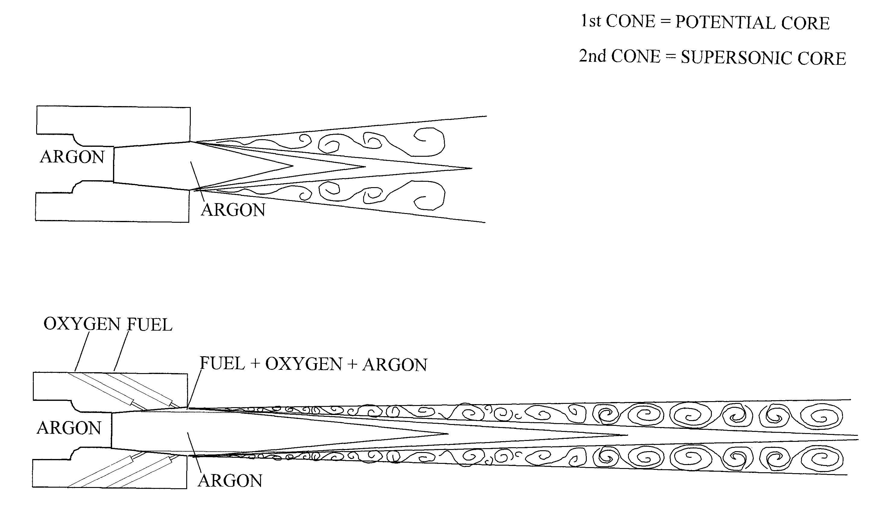
[0018]A flame envelope is produced that surrounds a jet of inert gas formed from the inner central region of the structured jet and that initially has the supersonic velocity. The flame envelope inhibits velocity decay and concentration decay of the jet of inert gas. Velocity would otherwise decay without the flame envelope due to interaction of the jet of inert gas with the furnace atmosphere. Such interaction also causes a dilution of the jet of inert gas to produce a concentration decay. As used herein and in the claims, the term “flame envelope” means a flame that surrounds the jet of inert gas and propagates along the length thereof by active combustion of the fuel and any reactants that may be present within the heated furnace atmosphere, wherein such combustion is supported in whole or in part by oxygen supplied by the structured jet of inert gas. In the present invention, the flame envelope is produced entirely outside of the nozzle through contact of the outer circumferential region of the structured jet with the heated furnace atmosphere. This contact creates a shear-mixing zone containing a flammable mixture composed of the fuel, the argon, the oxygen and the heated furnace atmosphere and auto-ignition of the flammable mixture through heat supplied by the heated furnace atmosphere.
[0020]Although not known in the prior art, a discharge of a structured jet, such as described above, when contacted by the heated furnace atmosphere will produce a region within an outer shear-mixing zone that will ignite to form a flame envelope that will surround and inhibit velocity decay and concentration decay of a supersonic jet of inert gas formed by the inner central region of the structured jet. This allows a nozzle of the present invention to be positioned at some distance away from the melt and allows the beneficial stirring action of the melt to be enhanced.
[0021]As indicated above and as known in the prior art, the production and injection of a jet of inert gas while at a supersonic velocity has the advantage of minimizing any oxidization of the metal contained within the melt for refining purposes while at the same time producing a vigorous stirring action of the melt. Additionally, there are no external fuel passages that can plug requiring removal of the lance from service and extraction of deposits, known as skull, from the face of the nozzle. Furthermore, as can be appreciated from the above discussion, the disadvantages of mixing, igniting, stabilizing and combusting an oxygen and fuel containing stream at high velocity within a combined space (nozzle) are avoided by the present invention because ignition, stabilization and combustion of the mixture of fuel and oxygen is prevented while within the nozzle.
[0022]The combined fuel, inert gas and oxygen containing stream can be fully expanded upon discharge thereof as the structured jet from the nozzle. The fuel can be introduced to inert gas and oxygen containing stream while within the diverging section of the nozzle. As a safety measure, the combined fuel, inert gas and oxygen containing stream can be over expanded upon the discharge thereof as the structured jet from the nozzle such that the stream has a sub-ambient pressure while within the diverging section of the nozzle. The fuel can be introduced into the inert gas and oxygen containing stream at a location within the diverging section at which the inert gas and oxygen containing stream is at the sub-ambient pressure. As a result, upon failure of the fuel supply system, inert gas and oxygen will not back-flow through fuel passages creating a potentially dangerous condition. Another beneficial result is the fuel delivery system is not required to overcome positive back-pressure in the nozzle, thereby minimizing the supply pressure required for fuel delivery into the nozzle.

Problems solved by technology

However, the use of oxygen to form such coherent jets can result in oxidation of the steel and undesirable by-products.
For example, nitrogen may cause “nitrogen pickup” and add nitrogen into the steel, affecting the quality of the steel.
A problem arises when this method is applied to pure inert gas or high concentration inert gas, balance oxygen.
The internal shroud method is ineffective for producing coherent jets of inert gases due to the elimination or suppression of fuel combustion in the jet shear layer (i.e., combusting the injected fuel and oxygen in the shear layer to produce a coherent jet is not possible).
Therefore, a problem to solve is the production of coherent jets containing pure or a high concentration of inert gas, particularly argon, using the internal shroud technique.
Another problem to solve is the improvement of the refining of molten metal, particularly the basic oxygen process, by the application of internal shroud coherent jets containing argon.
As a result, this technique cannot be applied to produce argon coherent jets.
Because of the difficulties in applying an internal shroud method to an inert gas, it has not been achieved thus far.

Method used


Image

  • Injection method for inert gas
  • Injection method for inert gas
  • Injection method for inert gas

Examples


example 1

Argon Coherent Jets with Fuel

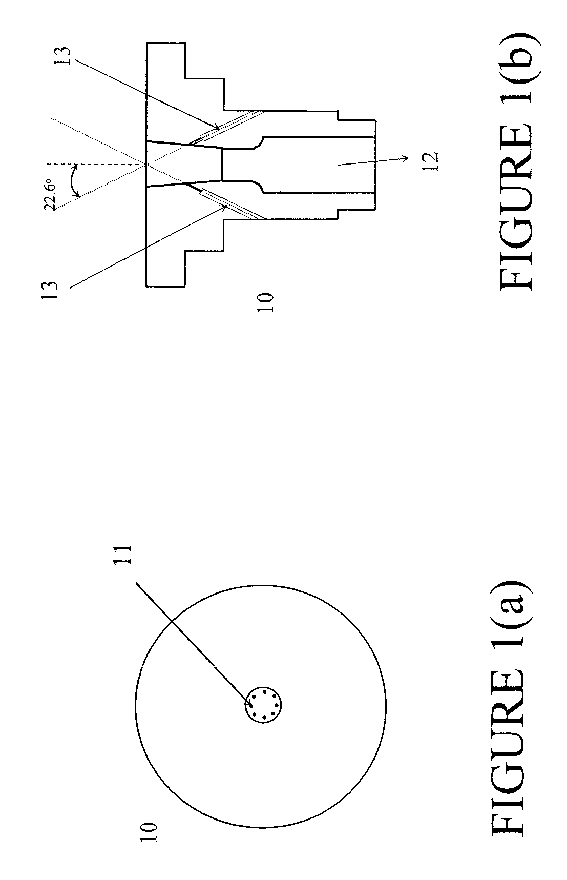
[0062]Experiments were conducted to try to produce a pure argon coherent jet injecting only internal shroud fuel. The internal shroud inert gas coherent jet injector used is illustrated in FIGS. 1(a) and 1(b). FIG. 1(a) is a view of the outlet of the injector (10) having eight ports (11), equally spaced. These ports are drilled holes and are each approximately 1 / 16 inch in diameter. FIG. 1(b) is a side cutaway view of the injector (10), showing a converging-diverging passageway (12) for the inert gas and passageways (13) that can be used for fuel or a mixture of fuel and oxygen.

[0063]The argon was injected at 100 psig and 3795 scfh and the fuel was natural gas (NG). The nozzle exit (D) and throat (T) diameters were 0.38-in. and 0.26-in., respectively. In a simulated furnace gas, the internal injection of fuel resulted in no change in jet length, as shown in Table 1.

[0064]

TABLE 1Argon With Internal Injection of FuelP.H.P.H.COInj.T.C.T.C.JetO2COFlowNGExitM...

example 2

Argon Coherent Jets with Oxygen and Fuel

[0067]In this set of experiments, the same injector design as in Example 1 was used and both oxygen and fuel were pre-mixed and injected via the passageways 13 into the internal shroud ports to try to produce a coherent argon jet. However, injecting only internal oxygen (up to 2% relative to the argon flow) and injecting both fuel (0.66%) and oxygen (0.97%) resulted in no changes in jet length (i.e., L / Lo=.about.1 for all experiments), as shown in Table 2.

[0068]

TABLE 2Argon With Internal Injection of Oxygen and FuelP.H.P.H.COInj.T.C.T.C.JetO2COFlowInj. NGO2ExitMidLength% NG / % O2 / (scfh)(scfh)(scfh)(scfh)(scfh)(° F.)(° F.)(in.)MAINMAINL / Lo116466051310.000.00189618129.880.000.001.00116466051310.0037.90NTNT10.000.001.001.01116466051310.0071.401868182410.000.001.881.011164660513180.600.00NTNT10.000.780.001.0111646605131103.1036.80NTNT10.000.660.971.01P.H. O2 = Preheat burner O2P.H. CO = Preheat burner COInj. NG = Injection of natural gasT.C. Exit =...

example 3

Injector with Porous Metal Distributor

[0069]Further experiments were run using the injector shown in FIG. 3. This injector (30) used a single porous metal (31), typically brass or bronze or copper, but any metal can be used, to evenly distribute a “pre-mixed” mixture of fuel and oxygen as the internal shroud gas into argon / oxygen main jets of varying compositions, including pure argon. The injector (30) comprises a converging / diverging passageway for the inert gas (32) and additional passageways (33) for fuel and oxygen to form the internal shroud. These experiments were conducted as single nozzle experiments and the converging / diverging passageway was designed to allow for oxygen flow at 4000 scfh (100 psig, Mach 2). In the experiments, the argon and oxygen were flowed between 3775-4000 scfh at 100 psig. The temperature at which the experiments were run was approximately 2250° F. (not corrected for radiation losses).

[0070]FIG. 4 is a graphical representation of the normalized jet l...


PUM


Abstract

A method and apparatus for forming internally shrouded supersonic coherent jets comprising an inert gas, such as pure argon and argon / oxygen mixtures. This method and apparatus can be employed to produce low-carbon steels with a top lance in basic oxygen steelmaking.

Description

CROSS-REFERENCE TO RELATED APPLICATION[0001]The present invention claims priority to U.S. provisional patent application Ser. No. 60 / 875,112 filed Dec. 15, 2006, and International Patent Application No. PCT / US2007 / 087607, filed on Dec. 14, 2007, the contents of which are incorporated herein by reference in its entirety.TECHNICAL FIELD[0002]The present invention generally relates to a method of injecting a supersonic coherent jet of an inert gas (either a pure inert gas or a high concentration of inert gas) into a molten metal bath located within a metallurgical furnace.BACKGROUND OF THE INVENTION[0003]In steelmaking, it is desirable to form coherent jets to promote mixing of the molten steel and to dilute the carbon monoxide (CO) in the molten steel and encourage the carbon and oxygen to come out of the steel. However, the use of oxygen to form such coherent jets can result in oxidation of the steel and undesirable by-products. Thus, it would be useful to form coherent jets from ine...

Claims


Application Information

Patent Timeline
Patent Type & Authority Patents(United States)
IPC IPC(8): C22B9/05
CPCC21C5/4606F23D14/22F23D14/32F27D3/16F23L7/00Y02P10/34F23L2900/07002Y02E20/344
Inventor MAHONEY, WILLIAM JOHNVARDIAN, GARY THOMAS
Owner PRAXAIR TECH INC
Why Eureka
Try Eureka