Bridging mechanism for peer-to-peer communication

Active Publication Date: 2013-06-11
APPLE INC
View PDF93 Cites 40 Cited by
  • Summary
  • Abstract
  • Description
  • Claims
  • Application Information

AI Technical Summary

Benefits of technology

[0007]Embodiments of the present invention are capable of being implemented in the context of a high-speed optical interface for connecting computers to external I/O devices. The interface allows a number of native I/O formats to be encapsulated into PCIe Vendor Defined Mess

Problems solved by technology

One thing lacking is support for peer-to-peer

Method used


Image

  • Bridging mechanism for peer-to-peer communication
  • Bridging mechanism for peer-to-peer communication
  • Bridging mechanism for peer-to-peer communication

Examples


Example

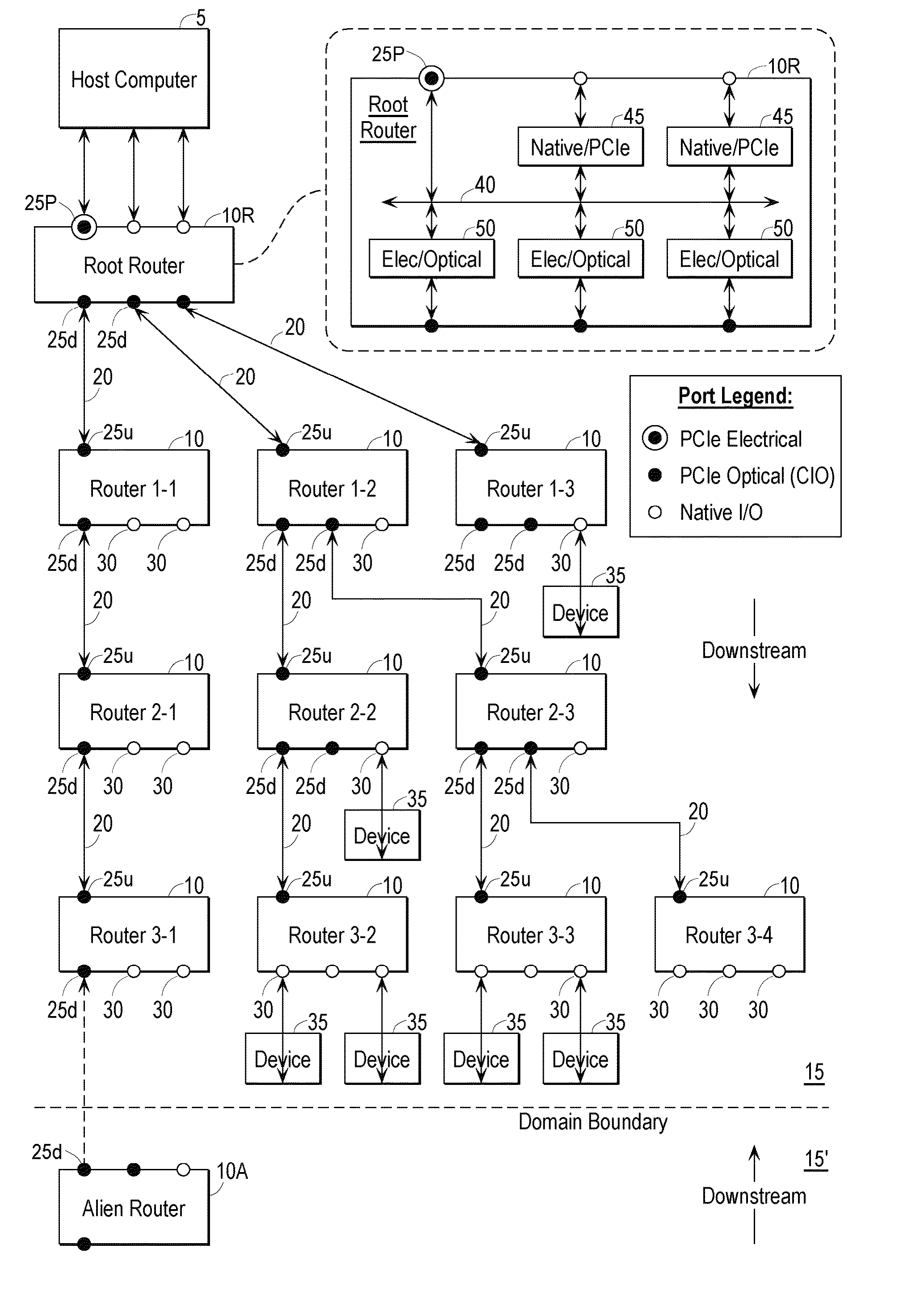
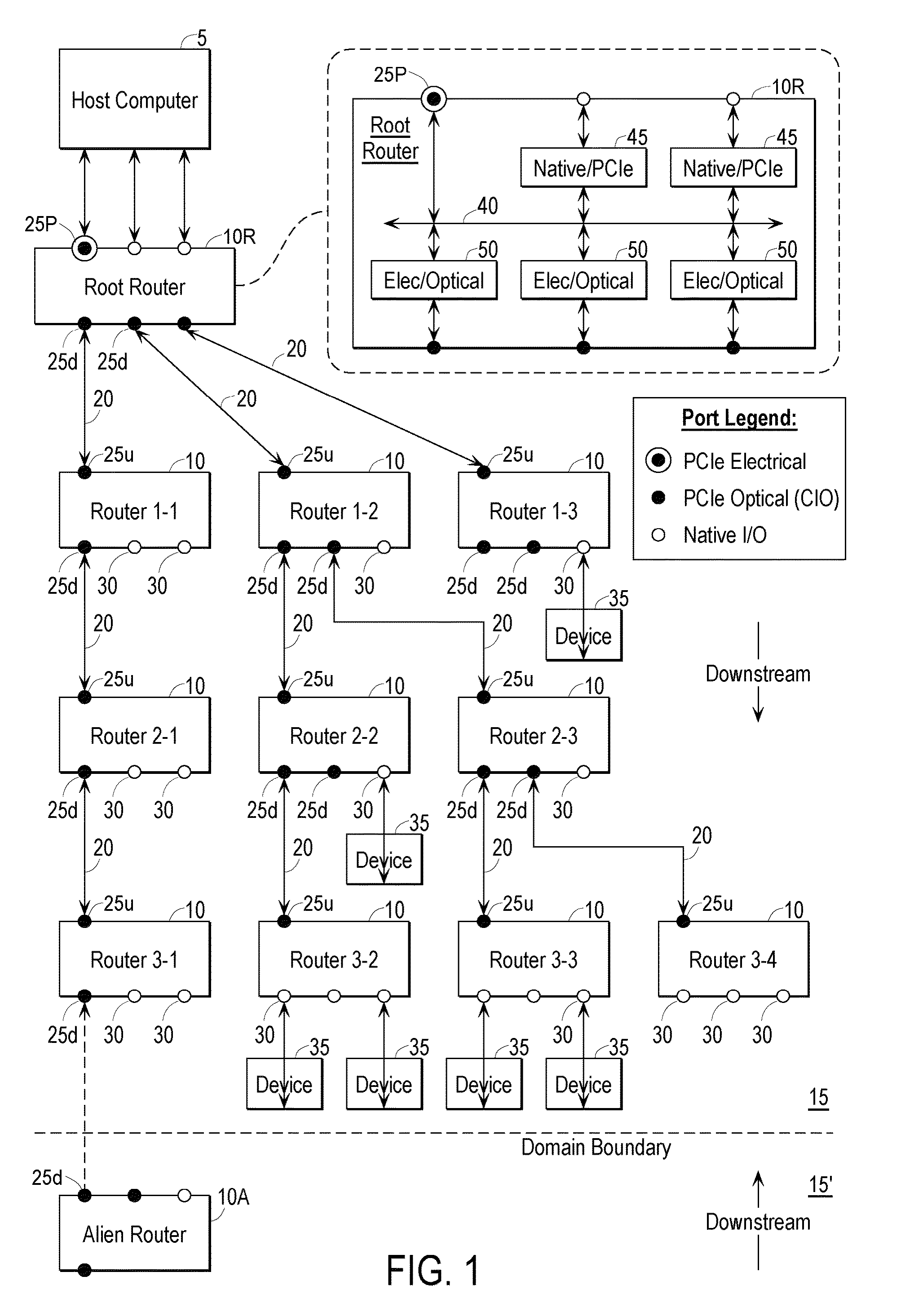
[0047]Embodiments of the present invention provide a high-speed optical interface for connecting computers to external I / O devices, including in some instances devices having bandwidth requirement in excess of common external interfaces. In a preferred embodiment, the interface is largely based on the industry-standard PCI Express (“PCIe”) interface, with extensions discussed below to provide additional functionality. The interface allows a number of native I / O formats to be encapsulated into PCIe Vendor Defined Messages (“VDMs”) for transfer over a single physical medium, preferably optical, and is thus referred to as the converged I / O (“CIO”) interface. In a specific implementation, optical links between devices support high-speed serial communications, and the data is in the form of PCIe packets.

[0048]FIG. 1 is a block diagram of a representative system according to embodiments of the present invention. The system includes a host computer 5 connected to a network of routers that ...


PUM


Abstract

A high-speed optical interface for connecting computers to external I/O devices allows a number of native I/O formats to be encapsulated into PCIe Vendor Defined Messages (“VDMs”) for transfer over a single physical medium, preferably optical, and is thus referred to as the converged I/O (“CIO”) interface. Standard PCIe bridges are modified to support peer-to-peer communications, allowing greater exploitation of the capabilities of PCIe.

Description

CROSS REFERENCE TO RELATED APPLICATIONS[0001]This application claims the benefit of U.S. Patent Application No. 60 / 997,248 filed Oct. 1, 2007 for “Converged Computer I / O System and Bridging Mechanism for Peer-to-Peer Communication” (inventors Paul A. Baker, Michael W. Murphy, Eric Werner Anderson, Colin Whitby-Strevens, David Ferguson, Keith Diefendorff, and Ron Hochsprung, the entire disclosure of which is herein incorporated by reference in its entirety for all purposes[0002]The present application incorporates by reference for all purposes the entire contents of U.S. patent application Ser. No. 12 / 239,742, titled CONVERGED COMPUTER I / O SYSTEM, filed Sep. 27, 2008.BACKGROUND OF THE INVENTION[0003]The present invention is relates generally to network communications, and more particularly to peer-to-peer communications.[0004]The Peripheral Component Interconnect (“PCI”) is a well established and widely deployed standard that specifies a computer bus for attaching peripheral devices ...

Claims


Application Information

Patent Timeline
IPC IPC(8): G06F15/177
CPCG06F13/4027H04L29/06G06F15/177H04L9/40
Inventor BAKER, PAUL A.MURPHY, MICHAEL W.ANDERSON, ERIC WERNERWHITBY-STREVENS, COLINFERGUSON, DAVIDDIEFENDORFF, KEITHHOCHSPRUNG, RONCORNELIUS, WILLIAM
Owner APPLE INC
Why Eureka
Try Eureka