

Low phase noise MEMS-based oscillator with bifurcation and parametric noise squeezing
- Summary
- Abstract
- Description
- Claims
- Application Information
AI Technical Summary
Benefits of technology
Problems solved by technology
Method used
Image

Examples
Embodiment Construction
[0010]Reference will now be made in detail to the presently preferred embodiments of the invention, examples of which are illustrated in the accompanying drawings.
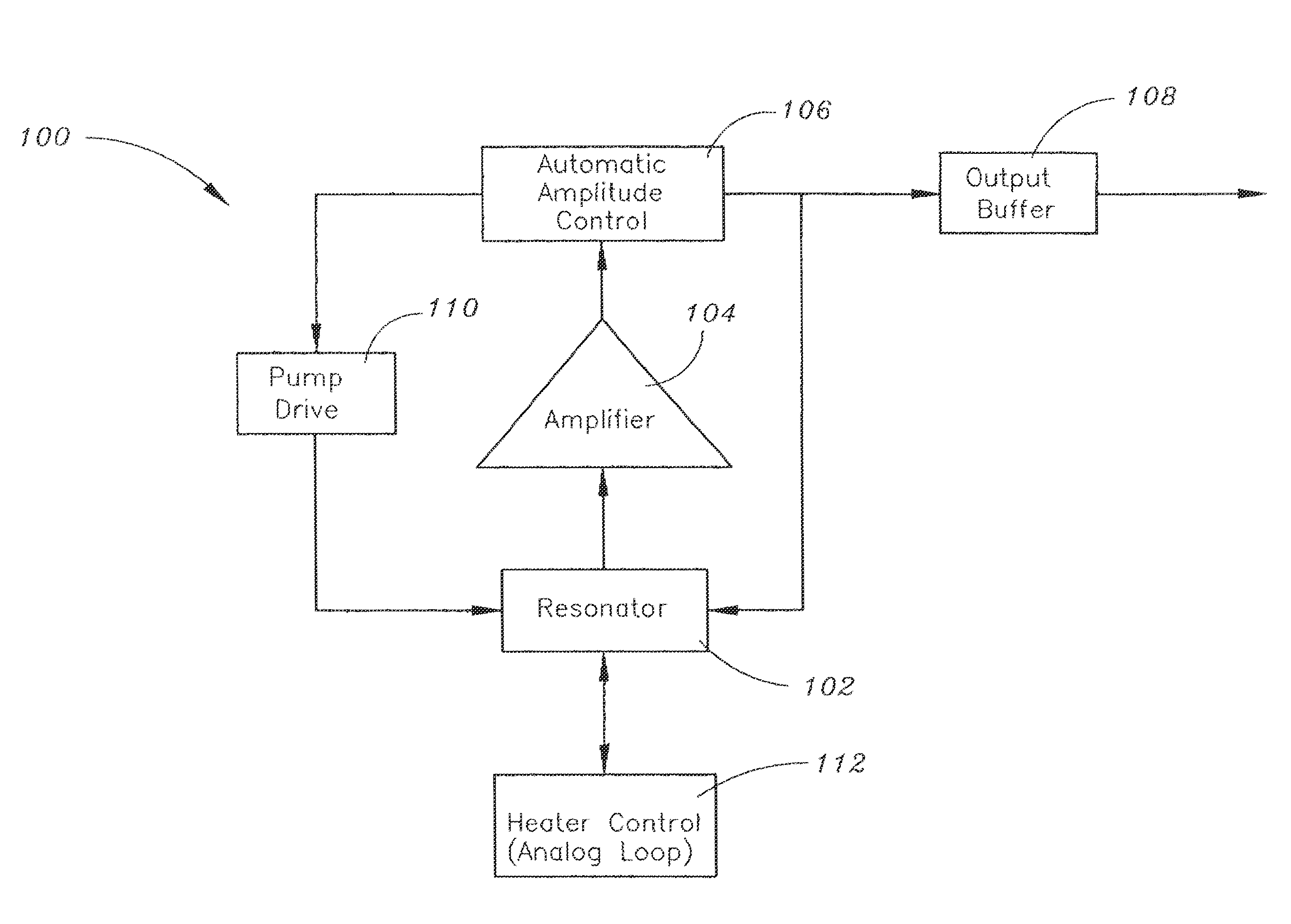
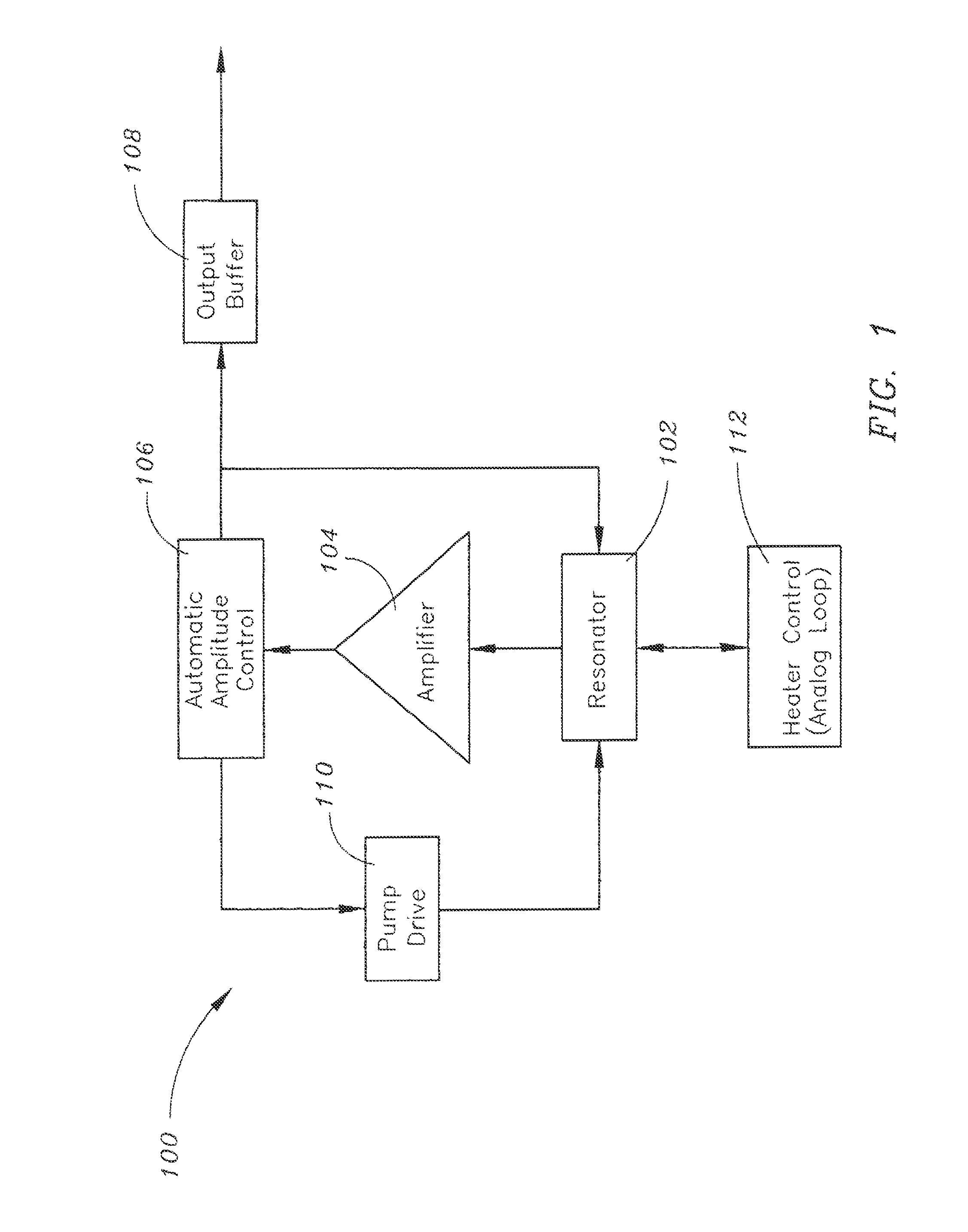
[0011]Referring to FIG. 1, an oscillator 100 in accordance with an exemplary embodiment of the present disclosure is shown. The oscillator 100 (exs.—an electronic oscillator, a microelectromechanical systems (MEMS)-based oscillator, a MEMS oscillator) may include a resonator 102. For instance, the resonator 102 may be a mechanical device and / or a microelectromechanical systems (MEMS)-based resonator 102 (ex.—a MEMS resonator 102). In exemplary embodiments, the electronic oscillator 100 may be an electronic circuit which is configured for producing output signal(s) (exs.—oscillator output signal(s), repetitive electronic signal(s), such as sine wave(s) or a square wave(s)). In further embodiments, the oscillator 100 may be configured for implementation in electronic device(s). In still further embodiments, the resonator 102...
PUM
 Abstract
Description
Claims
Application Information