
Panel fixing device

a technology for fixing devices and panels, applied in heat-proofing, parkings, walls, etc., can solve the problems of complex installation process, inability to apply the anchor bolts to the rear surface of the panel, and the inability to easily install the panel, so as to reduce the construction period and facilitate the installation. , the effect of rapid and easy installation

Inactive Publication Date: 2013-06-25
KIM JONG SUNG
View PDF5 Cites 56 Cited by
  • Summary
  • Abstract
  • Description
  • Claims
  • Application Information

AI Technical Summary

Benefits of technology

The present invention provides a panel fixing device that allows for easy and rapid installation of panels, reducing construction periods. Additionally, the device includes a connecting plate and auxiliary holes that enable easy replacement of panels when partially broken, improving maintenance.

Problems solved by technology

However, the conventional panel fixing device can be applied only to the panel having the pin installation grooves formed in an upper surface and a lower surface thereof but cannot be applied to the panel having the anchor bolts protruding from the rear surface thereof.
In addition, in the conventional panel fixing device, the pin installation grooves are formed in the upper surface and the lower surface of the panel in the construction site, the pin installation grooves formed in the upper surface of the panel disposed at a lower side are aligned with the pin hole of the adjustment bracket, and then, the fixing pin is inserted to align an upper protrusion of the fixing pin with the pin installation groove of the lower surface of the panel, which is to be disposed at an upper side, and thus an installation process is complicated and the panel cannot be easily installed.
Further, when any one of the plurality of panels installed at the wall of the building in vertical and horizontal directions is broken, due to a structure in which neighboring panels in the vertical direction are fixed by the fixing pins, the broken panel cannot be easily replaced with a new one, and thus, maintenance after installation of the panels cannot be easily performed.

Method used


Image

  • Panel fixing device
  • Panel fixing device
  • Panel fixing device

Examples


Embodiment Construction

[0031]Hereinafter, an exemplary embodiment of a panel fixing device in accordance with the present invention will be described in detail with reference to the accompanying drawings.

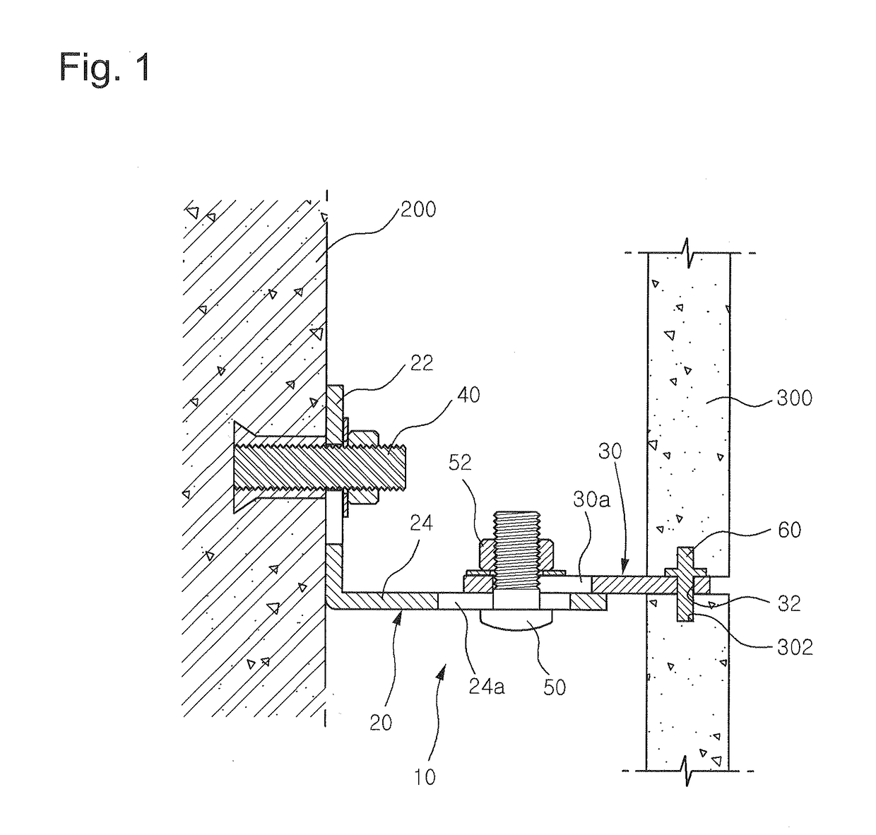
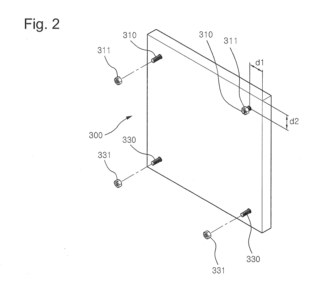
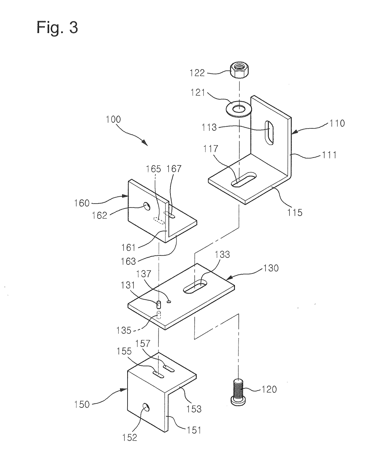
[0032]FIG. 2 is a view showing an example of a panel having anchor bolts installed at corners of a rear surface thereof and fixed by a panel fixing device in accordance with the present invention, FIG. 3 is an exploded perspective view showing a coupling structure of the panel fixing device in accordance with the present invention, FIG. 4 is an assembled cross-sectional view showing the coupling structure of the panel fixing device in accordance with the present invention, FIG. 5 is an exemplary view showing a first step of exchanging a panel damaged in use of the panel fixing device in accordance with the present invention with a new one, FIG. 6 is an exemplary view showing a second step of exchanging the panel damaged in use of the panel fixing device in accordance with the present invention with a new ...


PUM


Abstract

Provided is a panel fixing device with which panels can be rapidly and easily installed to reduce a construction period and a broken panel can be easily replaced with a new one to easily perform maintenance of the panel. For this, the panel fixing device is configured to fix a plurality of panels having anchor bolts protruding rearward therefrom to a wall of a building and maintaining the panels to the wall of the building, and includes a wall-fixing bracket, a connecting plate, a first connecting bracket and a second connecting bracket, wherein a fixing pin and a support pin protrude upward and downward from a front side of the connecting plate, and an auxiliary hole, a first auxiliary long hole and a second auxiliary long hole are formed in the connecting plate, the first connecting bracket and the second connecting bracket to communicate with each other.

Description

BACKGROUND OF THE INVENTION[0001]1. Field of the Invention[0002]The present invention relates to a panel fixing device, and more particularly, to a panel fixing device, which includes a wall-fixing bracket, a connecting plate, a first connecting bracket and a second connecting bracket, wherein a fixing pin and a support pin protrude upward and downward from a front side of the connecting plate, and an auxiliary hole, a first auxiliary long hole and a second auxiliary long hole are formed in the connecting plate, the first connecting bracket and the second connecting bracket to communicate with each other. Thus, a panel can be rapidly and easily installed to reduce a construction period, and the panel can be easily changed with a new one to enable easy maintenance of the panel.[0003]2. Description of the Related Art[0004]In general, marble blocks, which are used as panels for construction and have a certain shape and size, are fixedly installed at a wall surface of a building by sepa...

Claims


Application Information

Patent Timeline
IPC IPC(8): E04B2/88E04F13/00E04C2/00E04B1/76E04B9/00
CPCE04F13/0835E04F13/14E04F13/0855
Inventor KIM, JONG SUNG
Owner KIM JONG SUNG
Learn More