Pavement cutting apparatus and method

a cutting apparatus and pavement technology, applied in cutting machines, roads, construction, etc., can solve the problems of pavement cutting equipment moving laterally, dragging of the offset rotary saw blade of pavement cutting equipment, shortening the service life, etc., to reduce the amount of rotary stress on the rotary, shorten the service life of the rotary saw blade, and eliminate the effect of spalling

Active Publication Date: 2013-06-25
SCHABACKER NOLAN D
View PDF7 Cites 4 Cited by
  • Summary
  • Abstract
  • Description
  • Claims
  • Application Information

AI Technical Summary

Benefits of technology

[0005]With the structure of the pavement cutting apparatus of the subject invention, a cut is formed in a pavement along a desired line by aligning the pivot-axis of the coupling of the pavement cutting apparatus with the intended cut-line and maintaining the pivot-axis of the coupling aligned with and moving along the intended cut-line while a cut is being made in the pavement with the pavement cutting apparatus. With this structure, when the cutter-mounting frame is being towed in the cutting direction of travel for the pavement cutting apparatus to form a generally vertically extending cut in a pavement: the saw blade of each of the one or more cutter assemblies follows the vertical or substantially vertical pivot-axis of the coupling; the rotary saw blade of each of the one or more cutter assemblies is aligned with and contained in a common plane with the vertical or substantially vertical pivot-axis of the coupling; where there are a plurality of the cutter assemblies mounted on the cutter-mounting frame, the rotary saw blade of each of the cutter assemblies is aligned with and in the same plane as the rotary saw blade of each of the one or more other cutter assemblies; and any oblique inclination of the rotary saw blade(s) of the pavement cutting apparatus to the direction of the cut being formed by the pavement cutting apparatus is eliminated or substantially eliminated even when the pavement is inclined laterally to the intended cut-line and the vehicle has to be oriented at an angle to the direction of the cut being made in the pavement with the rotary saw blade(s) so that the pavement cutting equipment continues to move in the direction of and along an intended cut-line. The elimination of any material oblique inclination of the rotary saw blade(s) of the pavement cutting equipment of the subject invention to the cut being formed in a pavement by the rotary saw blade(s): reduces the amount of stress on the rotary saw blade(s) that would otherwise shorten the service life of the rotary saw blade(s); can prevent a breakout of the center(s) of the rotary saw blade(s) during service; and can reduce or essentially eliminate spalling (chipping) of the cut edges at the pavement surface which would adversely affect the appearance of the cut.
[0006]Where two or more cutter assemblies are mounted on the cutter-mounting frame, the rotary saw blades of the cutter assemblies normally successively increase the depth of the cut being made in the pavement by the cutter assemblies, e.g. through the use of successive cutter assemblies with successively greater diameter rotary saw blades and / or through the use of successive cutter assemblies with rotary saw blades having axes of rotation that are successively lower. The cutting depth of the rotary saw blade of any one or more or all of the cutter assemblies can be adjustable independently of the rotary saw blades of the other of the cutter assemblies.

Problems solved by technology

With this structure, the cutting of a pavement with the offset rotary saw blade of the pavement cutting equipment produces a drag on the side of the pavement cutting equipment where the offset rotary saw blade is located.
If there is no compensation for this drag, the drag will cause the pavement cutting equipment to move laterally to the direction of the intended cut-line.
The oblique inclination of the rotary saw blade of the pavement cutting equipment to the cut being formed in the pavement by the rotary saw blade: places stresses on the rotary saw blade that shortens the service life of the rotary saw blade; can cause the center of the rotary saw blade to break out; and causes spalling (chipping) of the cut edges at the pavement surface which adversely affects the appearance of the cut.

Method used


Image

  • Pavement cutting apparatus and method
  • Pavement cutting apparatus and method
  • Pavement cutting apparatus and method

Examples


Embodiment Construction

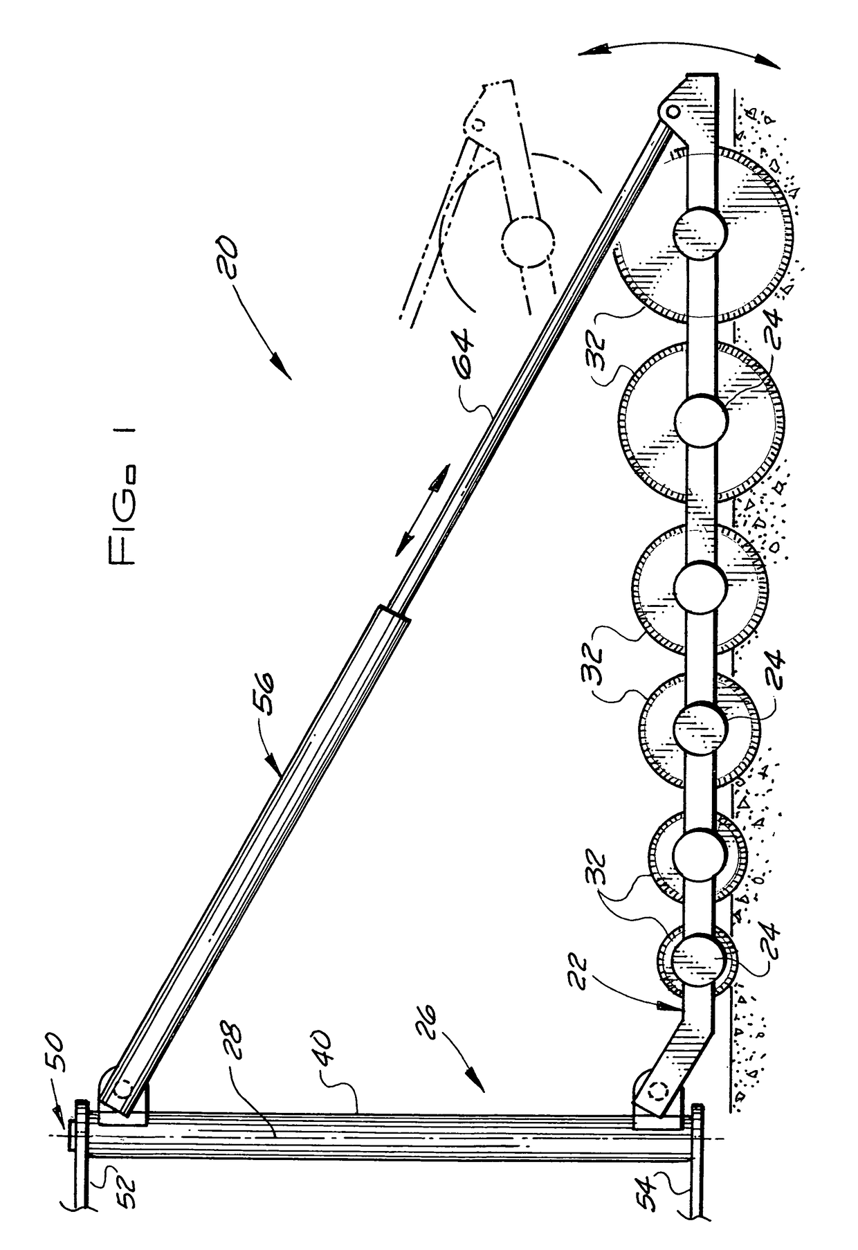
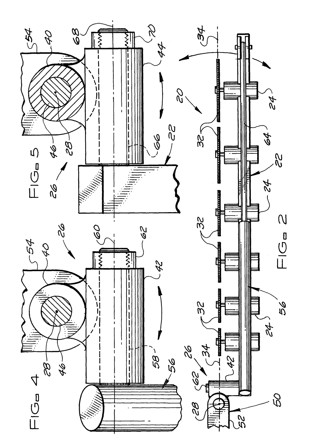
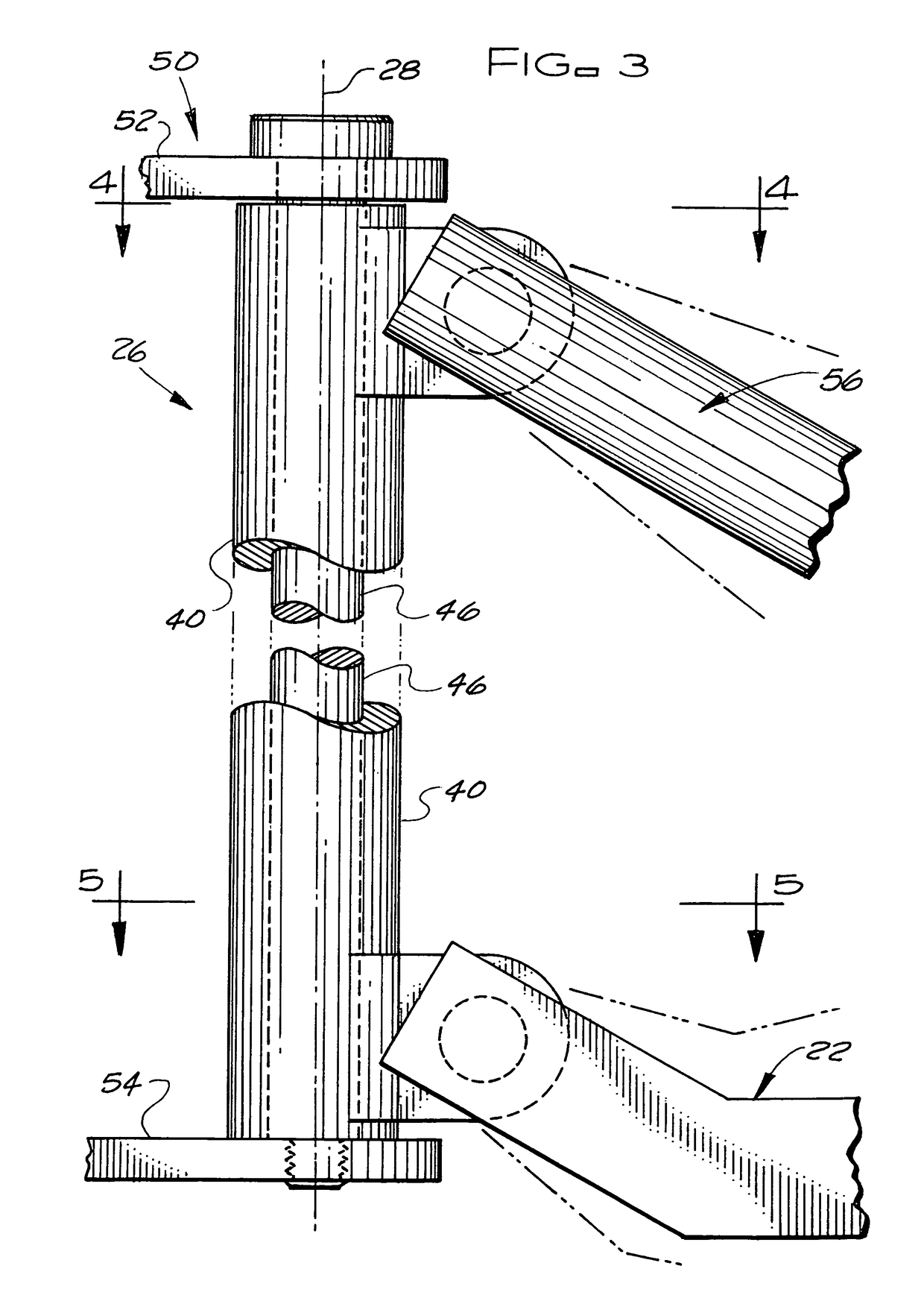
[0014]The pavement cutting equipment of the subject invention for cutting a concrete or asphalt pavement has one or more pavement cutting apparatuses 20. As shown in FIGS. 1 and 2, the pavement cutting apparatus 20 of the subject invention for cutting a concrete or asphalt pavement has a leading end mounted cutter-mounting frame 22 with one or more cutter assemblies 24 mounted thereon for making a cut, e.g. a joint or other cut, in a pavement. The cutter-mounting frame 22 has a leading end and a trailing end relative to a cutting direction of travel for the pavement cutting apparatus 20 when the pavement cutting apparatus 20 is cutting a pavement. The pavement cutting apparatus 20 has a coupling 26 for pivotally connecting the leading end of the cutter-mounting frame 22 to a towing vehicle for towing the pavement cutting apparatus 20 so that the cutter-mounting frame 22 pivots about a vertical or substantially vertical pivot-axis 28 of the coupling 26. Each of the one or more cutter...


PUM

PropertyMeasurementUnit
depthaaaaaaaaaa
cutting depthaaaaaaaaaa
angleaaaaaaaaaa

Abstract

A pavement cutting method and apparatus for cutting a concrete or asphalt pavement utilizes one or more cutter-mounting frames having one or more cutter assemblies mounted thereon for making a cut in a pavement. The leading end of each frame has a coupling for pivotally mounting the leading end of the frame to a towing vehicle for towing the frame so that the frame pivots about a vertical or substantially vertical pivot-axis passing through the coupling. Each of the one or more cutter assemblies has a driven rotary saw blade that is located in a common vertical or substantially vertical plane that contains the vertical or substantially vertical pivot-axis of the coupling whereby the saw blade of each of the one or more cutter assemblies follows the pivot-axis of the coupling when the frame is being towed in the cutting direction of travel for the pavement cutting apparatus.

Description

BACKGROUND OF THE INVENTION[0001]The subject invention relates a pavement cutting apparatus and method for cutting or cutting and forming grooves or joints in concrete and asphalt pavement and, in particular, to an improved pavement cutting apparatus and method which eliminates any material oblique inclination of the rotary saw blade(s) of the pavement cutting apparatus to the direction of the cut being formed (any “crabbing” of the rotary saw blade(s) of the pavement cutting apparatus) by the pavement cutting apparatus. The pavement cutting apparatus and method of the subject invention can be used for tasks such as but not limited to: forming a joint or joints in pavement, cutting a pavement so that sections of the pavement can be removed from the pavement, etc. As used herein, the term pavement includes pavement structures such as but not limited to roads, sidewalks, airport runways, industrial and commercial floors, parking lots, ramps, aprons, etc.[0002]Current pavement cutting ...

Claims


Application Information

Patent Timeline
Patent Type & Authority Patents(United States)
IPC IPC(8): E01C23/09
CPCE01C23/0933B28D1/048B28D1/045
Inventor SCHABACKER, NOLAN D.
Owner SCHABACKER NOLAN D
Why Eureka
Try Eureka