Enhanced operation diagnostics

a diagnostic and operation technology, applied in the field of industrial control diagnostics, can solve the problems of increasing development time, adding complexity to the hmi application, and difficulty in ascertaining the reason why a desired command issued by an hmi is being prevented from executing, and achieve the effect of simplifying the generation of status summaries

Active Publication Date: 2013-06-25
ROCKWELL AUTOMATION TECH
View PDF12 Cites 38 Cited by
  • Summary
  • Abstract
  • Description
  • Claims
  • Application Information

AI Technical Summary

Benefits of technology

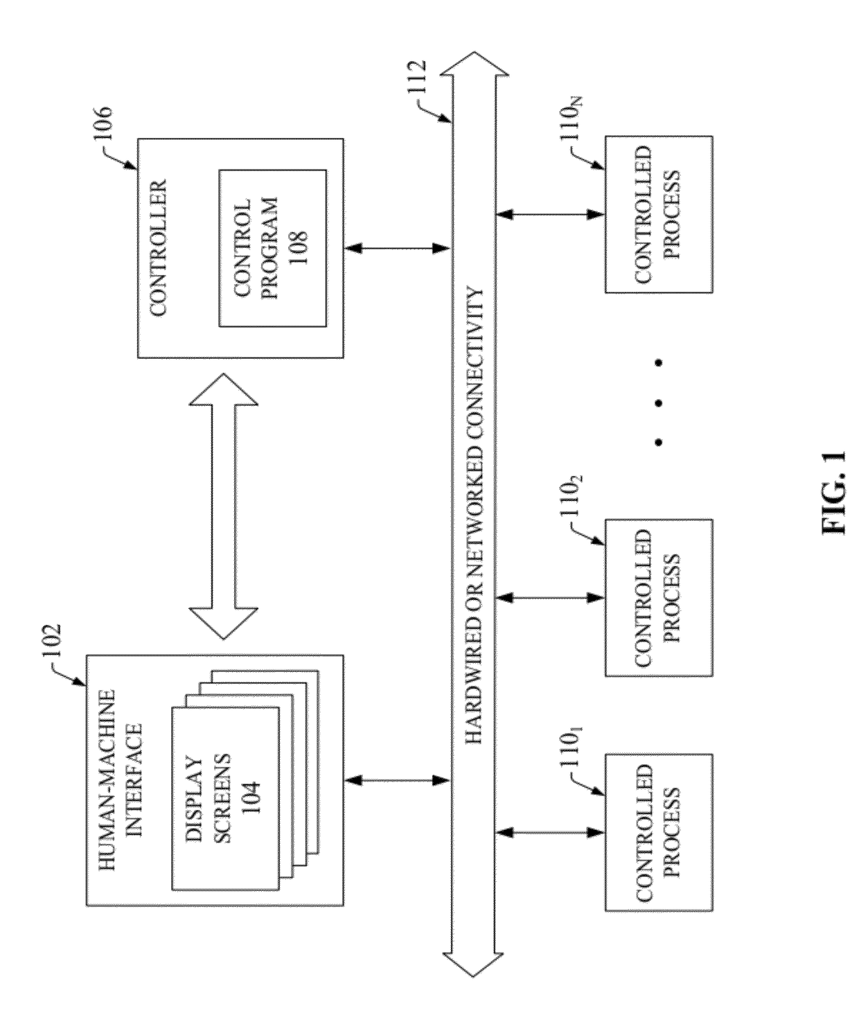
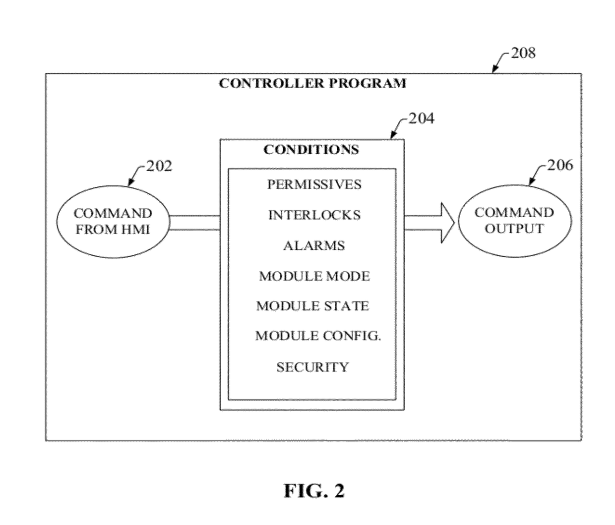
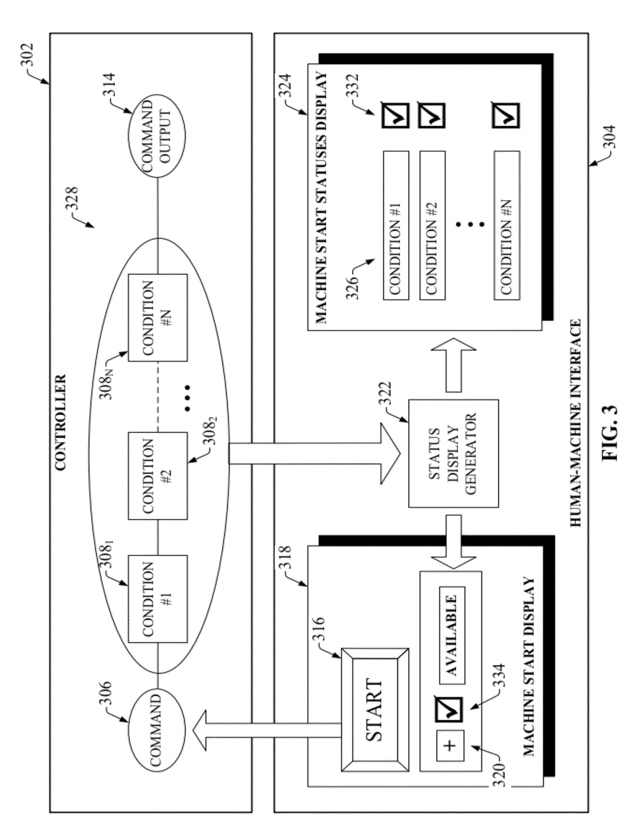
[0010]To simplify generation of status summaries, a status display generator is provided that can operate natively within the HMI software to generate and populate the summaries without the need to write extensive custom code in either the HMI or the control program. When an operator invokes a summary for a given command or module, the status display generator can poll the controller and determine both the identities and statuses of the set of conditions (e.g., permissives, interlocks, alarm conditions, etc) associated with the command. Using this information, the status display generator can create a summary display listing the conditions that must be satisfied before the command can be executed, as well as the present statuses of the respective conditions. This status display generator can thus generate condition summaries without the need for an HMI designer to create new custom display screens.

Problems solved by technology

However, from the point of view of a system operator, who typically is not involved in the system design process and therefore is not necessarily conversant with the low-level system interactions, these complex system dependencies often make it difficult to ascertain why a desired command issued by an HMI is being prevented from executing.
Although custom display screens can be developed for the HMI that list the conditions for a given action together with their respective states, such screens must be created and programmed by a system developer and manually linked to the program addresses associated with the respective conditions, increasing development time and adding complexity to the HMI application.

Method used


Image

  • Enhanced operation diagnostics
  • Enhanced operation diagnostics
  • Enhanced operation diagnostics

Examples


Embodiment Construction

[0027]The present invention is now described with reference to the drawings, wherein like reference numerals are used to refer to like elements throughout. In the following description, for purposes of explanation, numerous specific details are set forth in order to provide a thorough understanding of the present invention. It may be evident, however, that the present invention may be practiced without these specific details. In other instances, well-known structures and devices are shown in block diagram form in order to facilitate describing the present invention.

[0028]It is noted that as used in this application, terms such as “component,”“module,”“model,” and the like are intended to refer to a computer-related entity, either hardware, a combination of hardware and software, software, or software in execution as applied to an automation system for industrial control. For example, a component may be, but is not limited to being, a process running on a processor, a processor, an o...


PUM


Abstract

Systems and methods are provided that dynamically render permissive status information on a human-machine interface (HMI) to inform an operator of conditions that are preventing an issued control command from executing. A status display generator deployed on the HMI can be associated with a control action to be initiated in a control program via the HMI. The control action can have one or more programmed conditions or permissives that must be satisfied before the control action can be initiated. Operators wishing to review the states of the various conditions can invoke the status display generator, which reads the conditions and their respective statuses from the control program and generates a permissive summary display listing the conditions together with their respective “ready” or “not ready” states. The permissive summary display provides a convenient reference that allows the operator to quickly assess what actions must be taken to place the system in the appropriate state to execute the desired control action.

Description

TECHNICAL FIELD[0001]The claimed subject matter relates generally to industrial control diagnostics, and more particularly to visualization of permissive information to assist operators with diagnosing a disabled control operation.BACKGROUND[0002]Programmable automation controllers (PACs) and their associated control programming are at the heart of modern industrial automation systems. These controllers interact with field devices on the plant floor to carry out controlled processes relating to such objectives as manufacture of a product, movement of material through a system, and other such processes. The controllers typically exchange data with the field devices using native hardwired I / O or via a plant network such as Ethernet, Data Highway Plus, Devicenet, or the like. The controller receives any combination of digital or analog signals from the field devices indicating a current state of the devices (e.g., temperature, position, part presence or absence, fluid level, etc.), and...

Claims


Application Information

Patent Timeline
Patent Type & Authority Patents(United States)
IPC IPC(8): G06F9/44G06F11/00G05B11/01G05B19/18G05B15/00
CPCG05B23/0267
Inventor WEATHERHEAD, NORMAN A.MATHESON, MARK K.XU, HUI
Owner ROCKWELL AUTOMATION TECH
Why Eureka
Try Eureka