Manual dual end rotary driver of Z configuration

a dual-end, rotary driver technology, applied in the direction of screwdrivers, wrenches, manufacturing tools, etc., can solve the problems of insufficient torque, too slow, too fast, etc., and achieve the effect of reducing the cost of manual operation, and improving the accuracy of manual operation

Active Publication Date: 2013-07-02
MCELROY MFG
View PDF19 Cites 25 Cited by
  • Summary
  • Abstract
  • Description
  • Claims
  • Application Information

AI Technical Summary

Problems solved by technology

Most have drawbacks such as too slow, too fast, inadequate torque, heavy, fatigues user quickly, needs a power cord or power source.
A simple straight screw driver is slow, may require a very firm grip, fatigues the hand and arm quickly, and requires repeated stopping and regripping.
A ratcheting screw driver requires repeated stopping and reversing and also fatigues the hand and arm quickly.
It can be hard to hold this screw driver aligned and engaged with a screw.
The hose can get tangled or caught on things.
A corded electric driver may be heavy, requires connection to a power source via an electrical cord long enough to reach the work.
The cord may get tangled or caught on things.
Electric drivers should not be used in wet environments due to the potential for electric shock and cannot be used underwater unless of special sealed design.
Electric drivers can be noisy and objectionable in areas or situations requiring quiet, such as a library, workplace, hospital or stealth military operation.
A battery powered drill can be heavy, lack torque, and must be periodically recharged at a power source.
If the battery does not have a charge or loses charge then it can't be used until it is charged, which may take a long time.
An electric driver, even if variable speed and high torque, can be hard to control, especially when trying to apply sufficient torque to fully seat a screw then immediately stop rotation when fully seated.
This makes it hard to stop the drill when the screw is fully seated.
If not stopped at the correct time / position it may over tighten and damage the material receiving the screw, deform and damage the fastener drive, deform and damage the drive bit tip or break off the head of the fastener.
This does not allow fluid adjustments of speed and torque, such as is desired when screwing a sizeable screw into wood.
It can be hard to hold in alignment with and engaged with the object being rotated.
The tool will easily slip off the object to be rotated if not held against it.
This is especially true when the Z configuration is elongated for speed, the tool will tend to slip off the object being rotated.
Fasteners such as a Phillips head screw require an axial engagement force proportional to the torque being applied in order to keep the Phillips bit and screw head engaged, otherwise either may deform and be damaged (“cam out”), which can result in either being made unusable.
It does not provide for using both ends of the tool to rotate objects.
U.S. Pat. No. 2,712,765 Wrist-Motion Rotary Hand-Tool teaches the wrist motion but lacks any way to vary the handle position to vary speed and torque.
It can be hard to hold in alignment with and engaged with the object being rotated.
It is not able to develop much torque.
It can be hard to hold in alignment with and engaged with the object being rotated.
It does not provide for using both ends of the tool to rotate objects.
It does not allow for good control over the amount of torque applied to the object to be rotated.
It can be hard to hold in alignment with and engaged with the object being rotated.
It does not provide for using both ends of the tool to rotate objects.
This application works quietly whereas a drill motor can be noisy which is objectionable in some quiet situations such as a hospital, library, office or stealth military operation.

Method used


Image

  • Manual dual end rotary driver of Z configuration
  • Manual dual end rotary driver of Z configuration
  • Manual dual end rotary driver of Z configuration

Examples


fifth embodiment

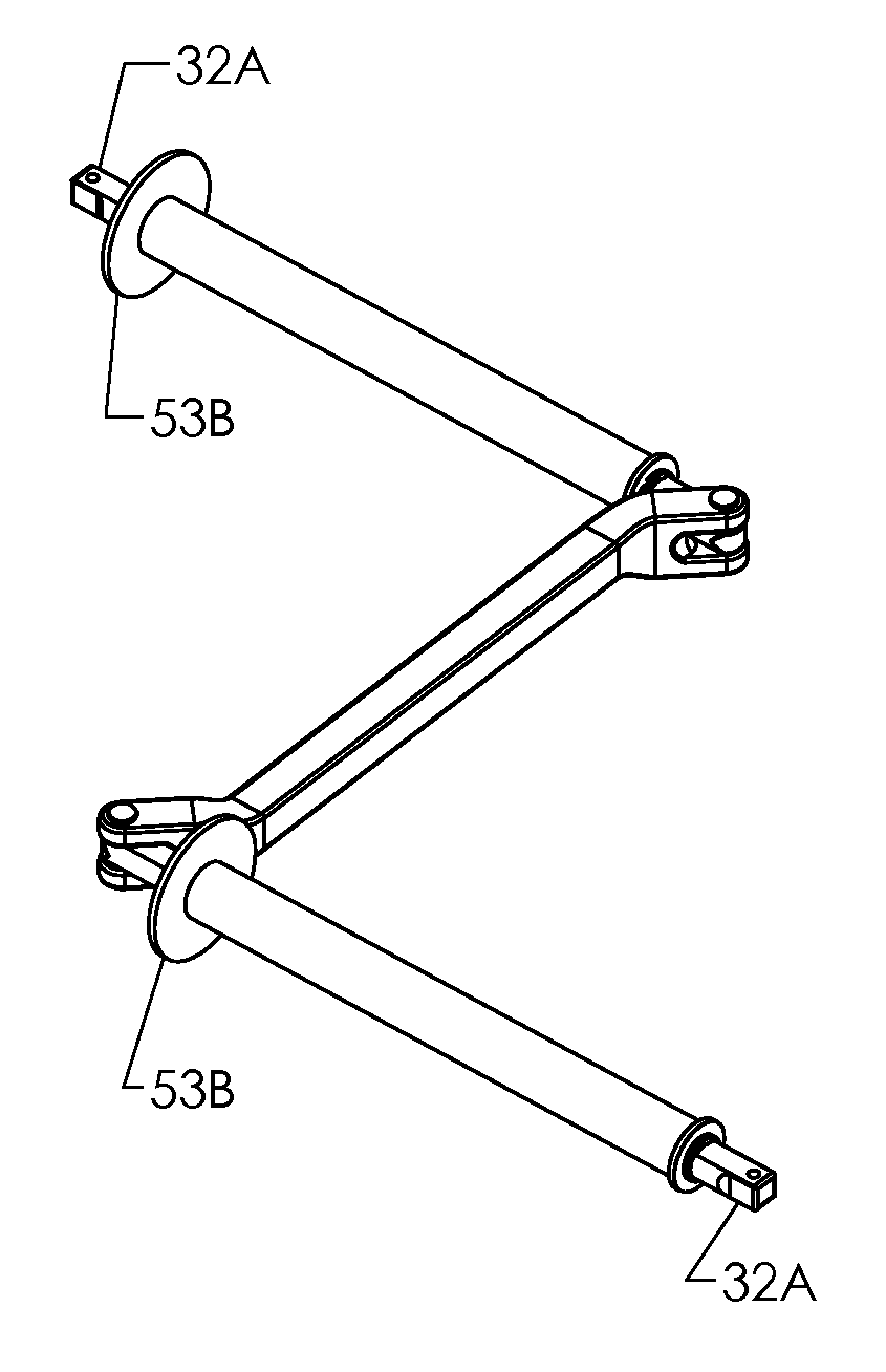
[0301]The operation of the fifth embodiment is similar to that of the fourth embodiment. FIG. 5A shows the positions of the sliding thrust flanges 53B when using the end shown at upper left to impart rotary motion. To use one end as the output member, slide its thrust flange 53B to the outboard end. Grasp its rotating handle 41A with the left hand L with thumb pointing towards the pivot and side of hand against the sliding thrust flange 53B. On the other end to be used as the input, slide its thrust flange 53B inboard towards the pivot. Grasp its rotating handle 41A with the right hand R, thumb pointing towards the pivot and thumb side of hand up against the thrust flange 53B. Use the left hand to steady the output member and keep it in axial alignment with and engaged with the object to be rotated. Use the right hand to position the input member in the desired configuration for speed, cranking, max torque or anything in-between and create the rotary motion and torque. In the cranki...

sixth embodiment

[0309]The operation of the sixth embodiment is similar to that of the fifth embodiment except that each hand is not placed against a thrust flange. Each handle 41A can be gripped anywhere along its length and tightly enough to impart the desired axial force via the friction between hand and handle 41A. FIG. 6C shows the tool in cranking configuration and with the square drive 32A end imparting the rotary motion.

[0310]FIG. 6D shows that it can be very compactly folded for storage into a volume approximately ½″×1⅜″×7″.

[0311]This embodiment is simple and comfortable to use and reduces frictional losses. It folds very compactly. All the axial force must be transmitted by the friction of the users grip on the handles 41A.

DETAILED DESCRIPTION

Seventh Embodiment—FIGS. 7A-M

[0312]FIGS. 7A-7E show a seventh embodiment. This embodiment is similar to the sixth embodiment but is larger, and has identical input / outputs, adds a flange bushing 55 pressed into each end of a rotating handle 41B, and e...

seventh embodiment

[0320]The operation is the same as the sixth embodiment. This embodiment further reduces the energy lost to friction and allows the tool to be used with greater ease. The bushings or bearings also act as the wearing parts that can be replaced.

[0321]The removable ball detent pin 51D allows fast and easy changing of the input / outputs or the connecting member 22B. The connecting member 22B could be changed to a shorter one to emphasize speed or a longer one to emphasize torque. Either input / output could be changed to one of a different drive size or type drive.

[0322]At present I believe that this seventh embodiment, with rotating handles 41B, flange bushings 55, and removable pins 51D gives the best combination of functionality and manufacturability for general use, but other embodiments are also satisfactory and their merit is best measured with respect to the end user's application and requirements and secondarily with respect to manufacturing and materials preferences.

DETAILED DESCR...


PUM


Abstract

Multiple embodiments of a manual tool, for ergonomic, controlled and variable application of rotary motion, torque, and or axial force to an object. One embodiment is comprised of three elongated members connected at their ends in a chain by two pivoted joints. The two outboard members each have an outboard end shaped for connecting to an object to be rotated and a rotatable handle. One way to use the tool is to grasp each handle with a hand; one hand holds the tool in axial alignment and engaged with the object to be rotated and the other hand orbits about the other handle. The three members can be fluidly positioned in a nearly straight Z, crank, L or in-line shape, so as to vary and control the speed, torque, and force. Either end of the tool may be used to rotate an object by swapping the tool end for end.

Description

CROSS-REFERENCE TO RELATED APPLICATION[0001]Not ApplicableFEDERALLY SPONSORED RESEARCH[0002]Not ApplicableSEQUENCE LISTING OR PROGRAM[0003]Not ApplicableBACKGROUND[0004]1. Field[0005]This application relates to hand tools used for applying rotary motion to objects, specifically to an improved manually operated, dual grip, dual end design that allows the rotational speed, direction, and torque to be ergonomically and easily applied, varied, and controlled.[0006]2. Prior Art[0007]Applying rotary motion to objects such as screws, bolts, sockets, hex bits, drill bits, shafts, generators, drives, etc. has been done via a multitude of manually operated and powered hand tools. Most have drawbacks such as too slow, too fast, inadequate torque, heavy, fatigues user quickly, needs a power cord or power source. A simple straight screw driver is slow, may require a very firm grip, fatigues the hand and arm quickly, and requires repeated stopping and regripping. A ratcheting screw driver require...

Claims


Application Information

Patent Timeline
Patent Type & Authority Patents(United States)
IPC IPC(8): B25B23/16
CPCB25G1/007B25G1/063
Inventor THOMAN, TIMOTHY MICHAEL
Owner MCELROY MFG
Why Eureka
Try Eureka