Pulling device and method therefor

a technology of pulling device and expander, which is applied in the direction of lifting equipment, pipe elements, mechanical equipment, etc., can solve the problems of large equipment used for pulling or pushing the expander through the pipe, large equipment in the industry for pulling or pushing the expander, and low cos

Active Publication Date: 2013-07-02
TTTECH
View PDF24 Cites 13 Cited by
  • Summary
  • Abstract
  • Description
  • Claims
  • Application Information

AI Technical Summary

Benefits of technology

[0008]The above mentioned problems such as low cost, light weight puller devices and systems adapted for use with small exit...

Problems solved by technology

For any number of reasons, an existing pipe may crack or break, necessitating replacement of the pipe.
Due to the size of pipe in these types of replacements, the equipment used for pulling or pushing the expan...

Method used


Image

  • Pulling device and method therefor
  • Pulling device and method therefor
  • Pulling device and method therefor

Examples


Embodiment Construction

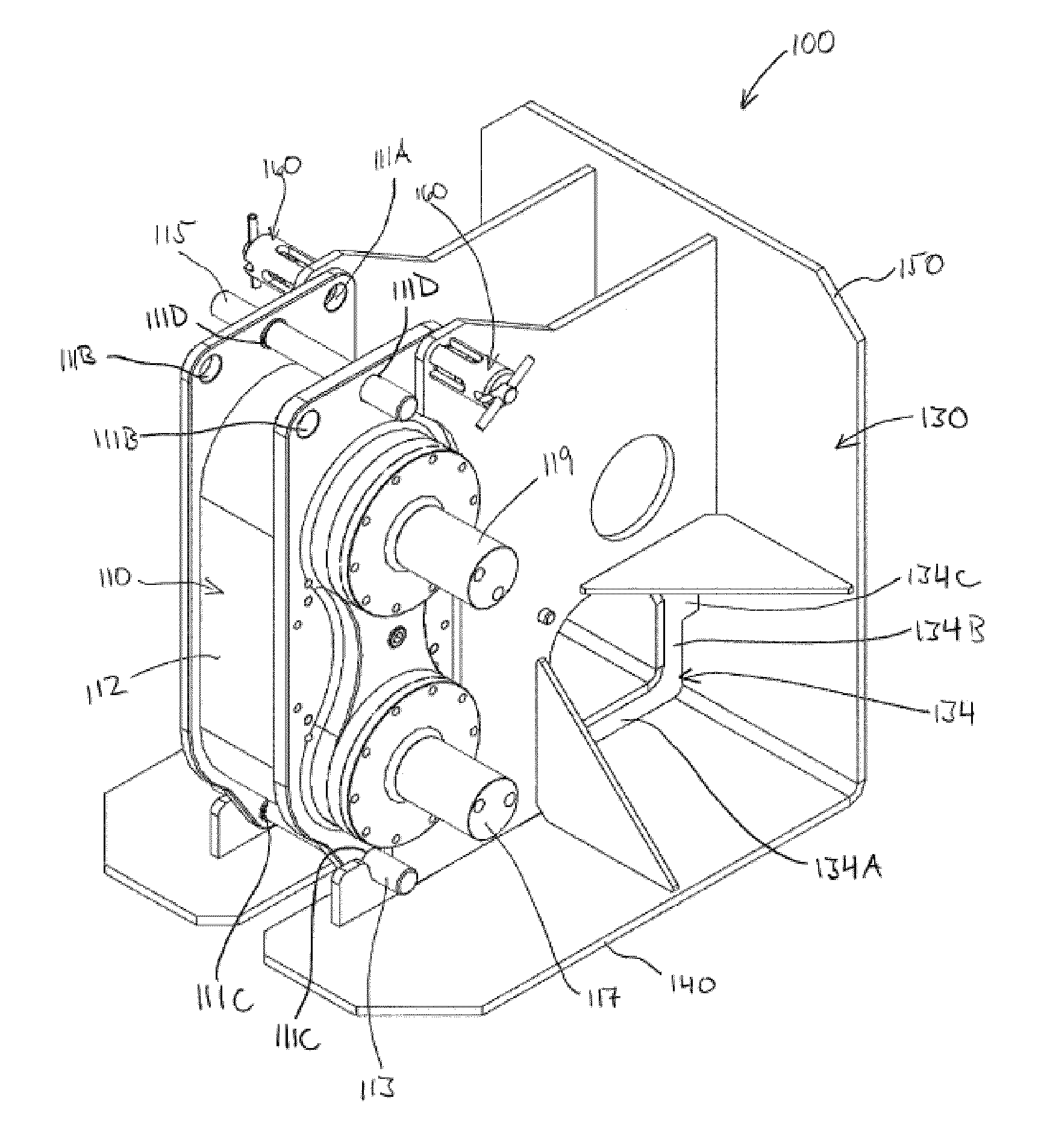
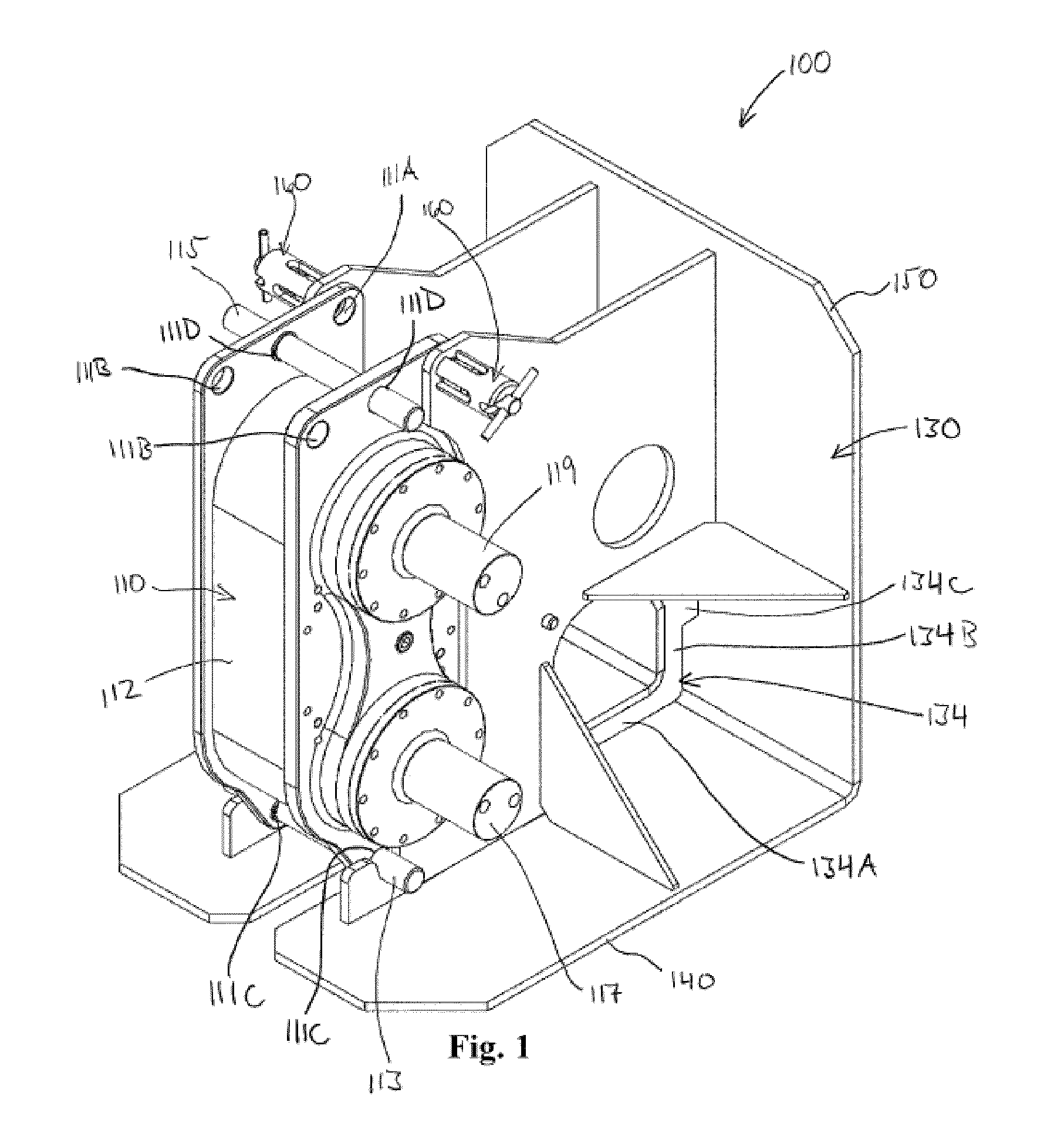
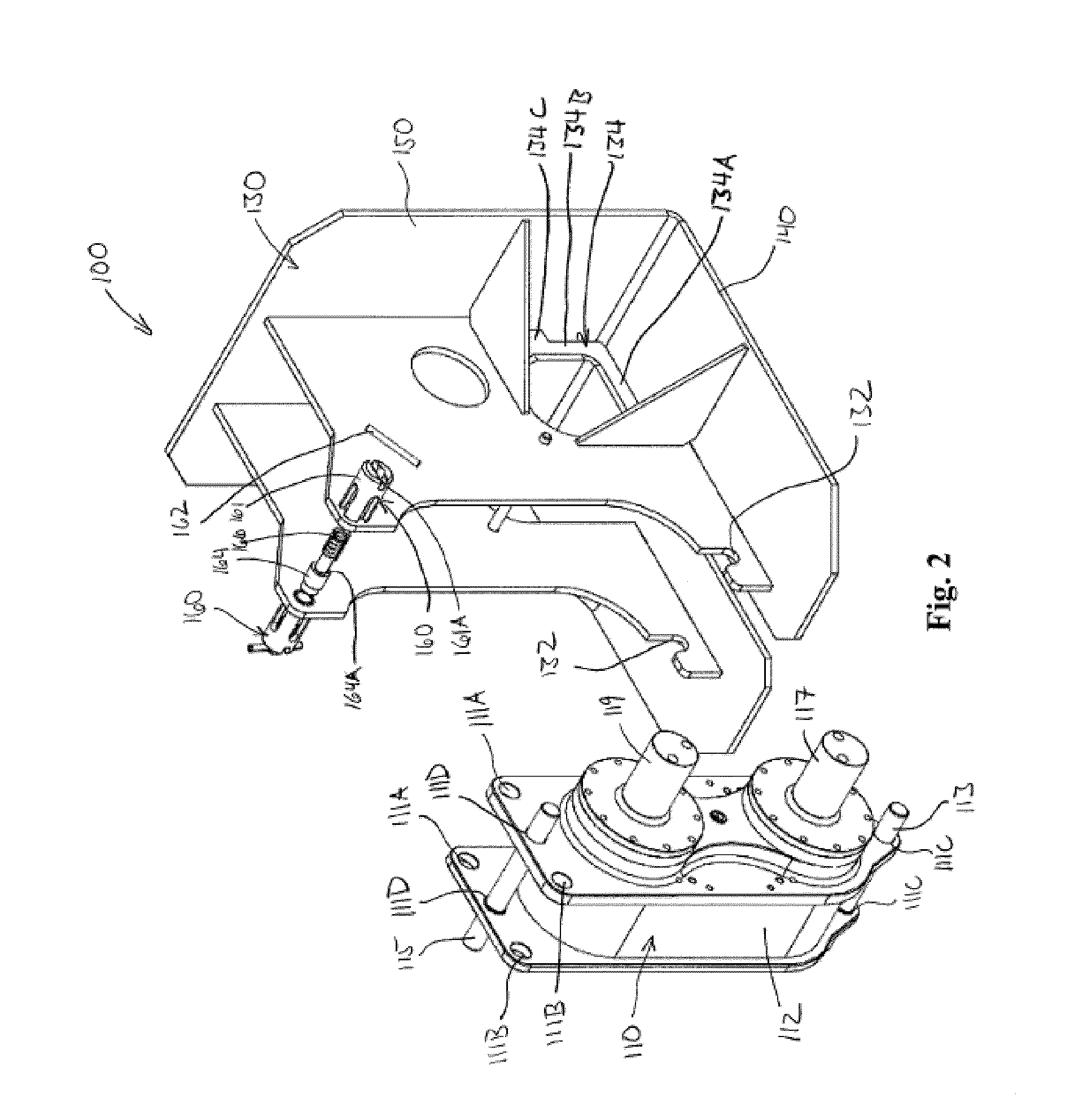
[0021]In the following detailed description, reference is made to the accompanying drawings which form a part hereof, and in which is shown, by way of illustration, specific embodiments in which the invention may be practiced. These embodiments are also referred to herein as “examples.” In the drawings, like numerals describe substantially similar components throughout the several views. These embodiments are described in sufficient detail to enable those skilled in the art to practice the invention. Other embodiments may be utilized and structural, or logical changes, etc. may be made without departing from the scope of the present invention.

[0022]All publications, patents, and patent documents referred to in this document are incorporated by reference herein in their entirety, as though individually incorporated by reference. In the event of inconsistent usages between this document and those documents so incorporated by reference, the usage in the incorporated reference(s) should...


PUM


Abstract

A puller is provided with a number of advantages. Pullers are described that have a high power to weight ratio, and a high power to volume ratio. Examples of pullers and pulling systems include configurations that provide high cable friction in a small device volume. Examples of pullers and pulling systems also include constant force pulling which is desirable in particular for small diameter pipe replacement. Using pullers and pulling systems as described, minimally invasive pipe replacement operations are possible. Reversible pullers are also provided that decrease the amount of time needed to burst or split multiple segments of pipe.

Description

RELATED APPLICATIONS[0001]This application claims the benefit of priority, under 35 U.S.C. §119(e), to U.S. Provisional Patent Application Ser. No. 61 / 097,372, filed on Sep. 16, 2008, which is incorporated herein by reference in its entirety.[0002]This application is related to U.S. patent application Ser. No. 11 / 215,316, entitled “DUAL CAPSTAN PULLER AND METHOD”, filed Aug. 29, 2005, the disclosure of which is incorporated herein by reference.TECHNICAL FIELD[0003]This invention relates to pulling equipment. Specifically, this invention relates to pulling equipment for use in trenchless pipe replacement.BACKGROUND[0004]Pipe materials such as cast iron, ductile iron, copper, etc. have been used for connecting homes and creating networks for utilities such as water, sewer, or gas, etc. For any number of reasons, an existing pipe may crack or break, necessitating replacement of the pipe.[0005]Trenchless pipe replacement is a currently known technique that replaces underground pipe with...

Claims


Application Information

Patent Timeline
IPC IPC(8): B66D1/36
CPCF16L55/18B66D1/26F16L55/1658
Inventor TJADER, MICHAEL
Owner TTTECH
Why Eureka
Try Eureka