Implantable medical sensor and fixation system

a technology of medical sensors and fixation systems, which is applied in the direction of rod connections, blood vessels, therapy, etc., can solve the problems affecting the operation and accuracy of the device, and achieve the effect of facilitating the operation of the device and minimizing invasiveness

Active Publication Date: 2013-07-02
MEDTRONIC VASCULAR INC
View PDF104 Cites 47 Cited by
  • Summary
  • Abstract
  • Description
  • Claims
  • Application Information

AI Technical Summary

Benefits of technology

[0007]In accordance with the invention, an implantable sensor is attached to a fixation member of wire-like construction that is expandable from a low profile configuration, in which a catheter can deliver it to the deployment site in the vessel, to an expanded configuration in which it is deployed in the vessel in engagement with the vessel wall. The fixation member may be formed from a highly resilient material, preferably one having superelastic properties and includes at least one linear attachment strut and at least one self-expandable portion. The sensor includes a housing with attachment elements adapted to receive the attachment strut in a manner that fixes the position of the sensor relative to the axis of the attachment strut and prevents the sensor housing from rotating about the strut. The housing of the sensor includes an elongate channel adapted to receive the attachment strut transversely. The channel may be defined in part by bendable tabs that are plastically deformed over the inserted attachment strut to secure the sensor housing and strut together. In another aspect of the invention the wire-like fixation member, including the expandable portion, is formed to lie in a single plane when expanded. The fixation member is dimensioned with respect to the intended deployment site so that when expanded it will engage the wall of the vessel at diametrically opposed locations in the vessel sufficiently to secure the fixation member and sensor housing to which it is attached, in place. In one embodiment of the invention the sensor housing may contain pressure sensing components including an externally exposed sensing element and is mounted to the fixation member such that, when the fixation member is deployed, the sensing element of the sensor will face along a direction generally perpendicular to the plane of the fixation member, to face inwardly toward the center of the vessel lumen and be exposed fully to the pressure within the vessel. In another embodiment the fixation member and sensor are arranged so that the sensing element faces generally parallel to the plane of the fixation member. The fixation member also may be configured to position the sensor housing and, particularly, the sensing element, away from the vessel wall to lessen the risk of turbulent flow through the vessel.
[0008]In a further aspect of the invention the fixation member includes at least one continuous loop integral with the attachment strut with the loop being non-circular, preferably somewhat teardrop-shaped, having narrow and broad ends. The narrow end is toward the middle of the fixation member with the broader portion located at the end of the fixation member where it can be engaged by a delivery device. The fixation member is formed from a superelastic material and the loop is compressible to a low delivery profile shape of a pair of approximately parallel wires. The narrow end of the teardrop loop is adapted to avoid excessive strain on that portion of the loop when the loop is compressed to its low profile, delivery shape.

Problems solved by technology

Depending on the nature, function and intended deployment site of the device, the manner in which the device is fixed in place and oriented in the body may affect the operation and accuracy of the device.

Method used


Image

  • Implantable medical sensor and fixation system
  • Implantable medical sensor and fixation system
  • Implantable medical sensor and fixation system

Examples


Embodiment Construction

[0040]The terms “distal” and “proximal” are used in the following description with respect to a position or direction relative to the treating clinician. “Distal” or “distally” are a position distant from or in a direction away from the clinician. “Proximal” and “proximally” are a position near or in a direction toward the clinician.

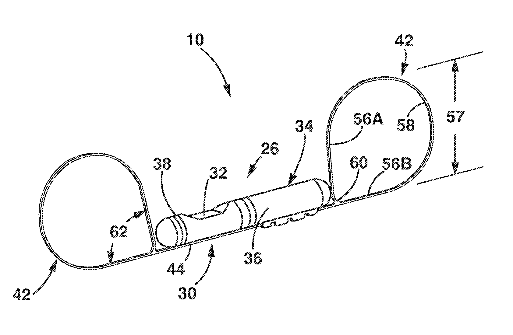
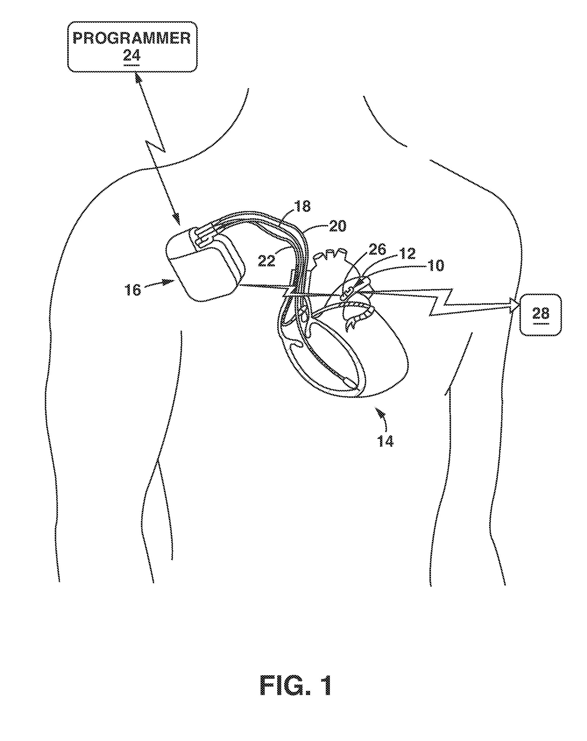
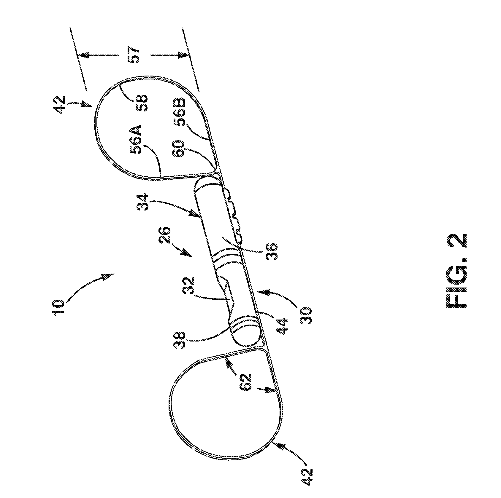
[0041]FIG. 1 illustrates, diagrammatically, a patient with implanted medical devices including a sensor assembly 10 implanted, for example, in the patient's pulmonary artery 12 through which blood flows from the heart 14 to the lungs, and another device, such as a pacemaker, defibrillator or the like, indicated generally at 16. For purposes of this description, knowledge of cardiovascular anatomy is presumed and details are omitted except to the extent necessary or desirable to explain the context of the invention. The device 16 may have a number of leads 18, 20, 22 that are placed in electrical contact with selected portions of the cardiac anatomy in or...


PUM

PropertyMeasurementUnit
junction angleaaaaaaaaaa
thicknessaaaaaaaaaa
widthaaaaaaaaaa

Abstract

An implantable medical device, such as a sensor for monitoring a selected internally detectable physiological parameter of a patient, is attached to a fixation member that is deployable within the patient to position and orient the sensor to enable it to perform its function. The fixation member may be configured to lie in a single plane when deployed or may be tubular in shape. The attachment of the housing and fixation member includes providing the fixation member with a linear attachment strut that is non-circular in cross section and providing the housing with external members that define an elongate channel, non-circular in cross section and receptive to the attachment strut. The attachment strut can be inserted transversely into the channel and the external member can be crimped over the strut to secure the housing and fixation member together.

Description

RELATED APPLICATIONS[0001]This application claims priority to provisional U.S. Patent Application Ser. No. 61 / 408,073, filed Oct. 29, 2010, entitled Medical Device Fixation Attachment Mechanism and to provisional U.S. Patent Application Ser. No. 61 / 437,198, filed Jan. 28, 2011, entitled Communication Dipole for Implantable Medical Device.FIELD OF THE INVENTION[0002]The invention relates to implantable medical sensors and fixation of such sensors in body lumens.BACKGROUND[0003]Various implantable medical devices have been clinically implanted or proposed for therapeutically treating or monitoring one or more physiological conditions of a patient. Such devices may be adapted to monitor or treat conditions or functions relating to heart, muscle, nerve, brain, stomach, endocrine organs or other organs and their related functions. Advances in design and manufacture of miniaturized electronic and sensing devices have enabled development of implantable devices capable of therapeutic as wel...

Claims


Application Information

Patent Timeline
Patent Type & Authority Patents(United States)
IPC IPC(8): A61B5/145
CPCA61B5/6876A61B5/6879Y10T29/49927F16B7/0433
Inventor SCHELL, JON D.PATRAS, GEORGEMOTHILAL, KAMAL DEEPGRISWOLD, ERIKALLAN, JAMES CALVINDUNFEE, ALBERTBEASLEY, RUDY
Owner MEDTRONIC VASCULAR INC
Why Eureka
Try Eureka