Angled reamer spindle for minimally invasive hip replacement surgery

a hip replacement and reamer spindle technology, applied in the field of angled reamer spindle for minimally invasive hip replacement surgery, can solve the problems of limiting mobility and the ability to perform daily living activities, requiring a longer recovery period and rehabilitation time for the patient, and being unsuitable for mis-adjustmen

Active Publication Date: 2013-07-02
VIANT AS&O HLDG LLC
View PDF49 Cites 29 Cited by
  • Summary
  • Abstract
  • Description
  • Claims
  • Application Information

AI Technical Summary

Benefits of technology

[0009]In accordance with still another embodiment, the elongate housing portion meets the distal neck portion at a rounded low profile surface configured to inhibit trauma to muscle tissue during use of the reamer spindle.

Problems solved by technology

The usual reasons for hip replacement are osteoarthritis, rheumatoid arthritis and traumatic arthritis, all of which can cause pain and stiffness that limit mobility and the ability to perform daily living activities.
However, such procedures require a longer recovery period and rehabilitation time for the patient.
However, reamer spindles have typically been straight and used in surgical exposures that cut quite a bit of muscle and are, therefore, unsuitable for MIS approaches.

Method used


Image

  • Angled reamer spindle for minimally invasive hip replacement surgery
  • Angled reamer spindle for minimally invasive hip replacement surgery
  • Angled reamer spindle for minimally invasive hip replacement surgery

Examples


Embodiment Construction

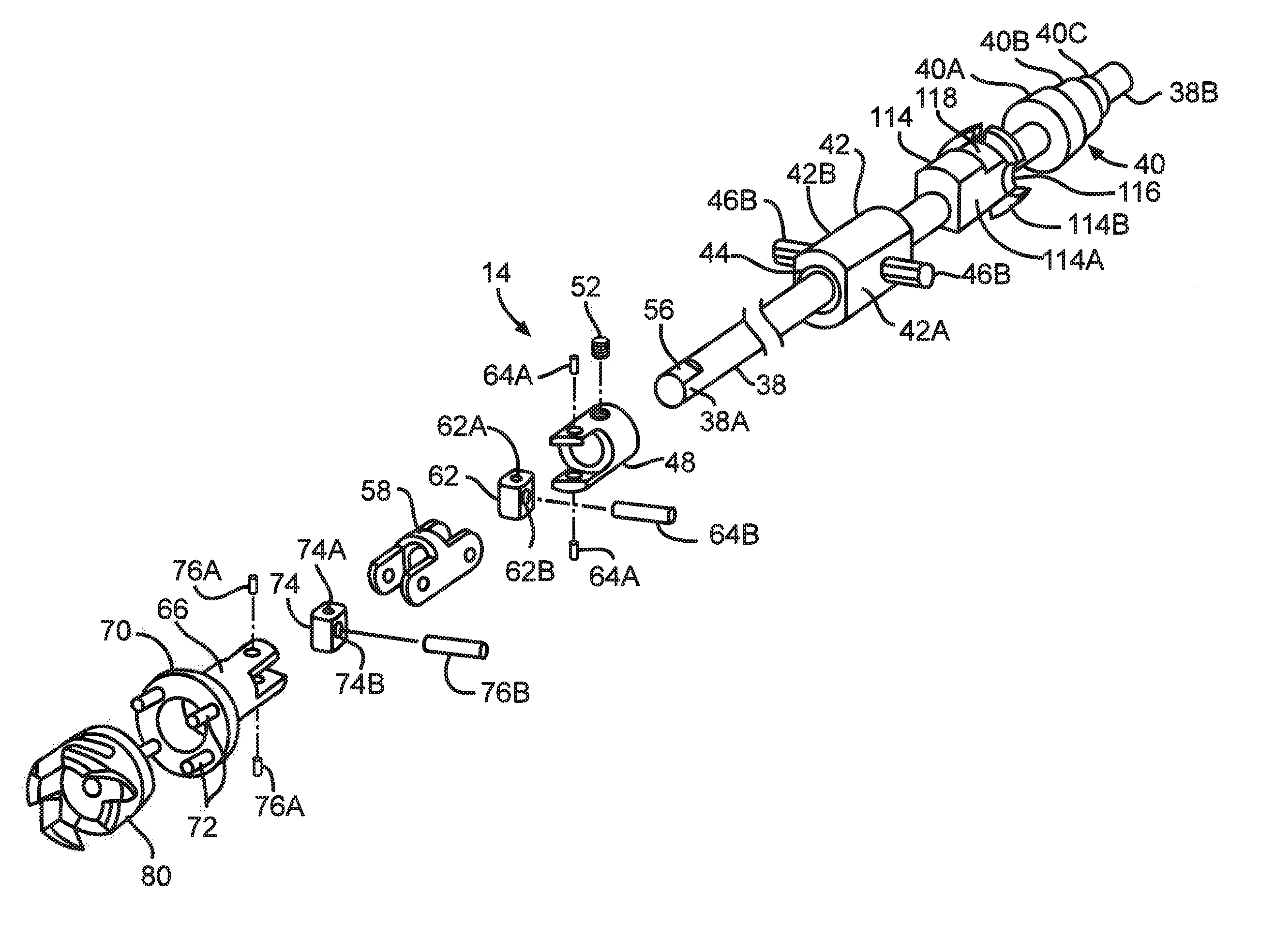
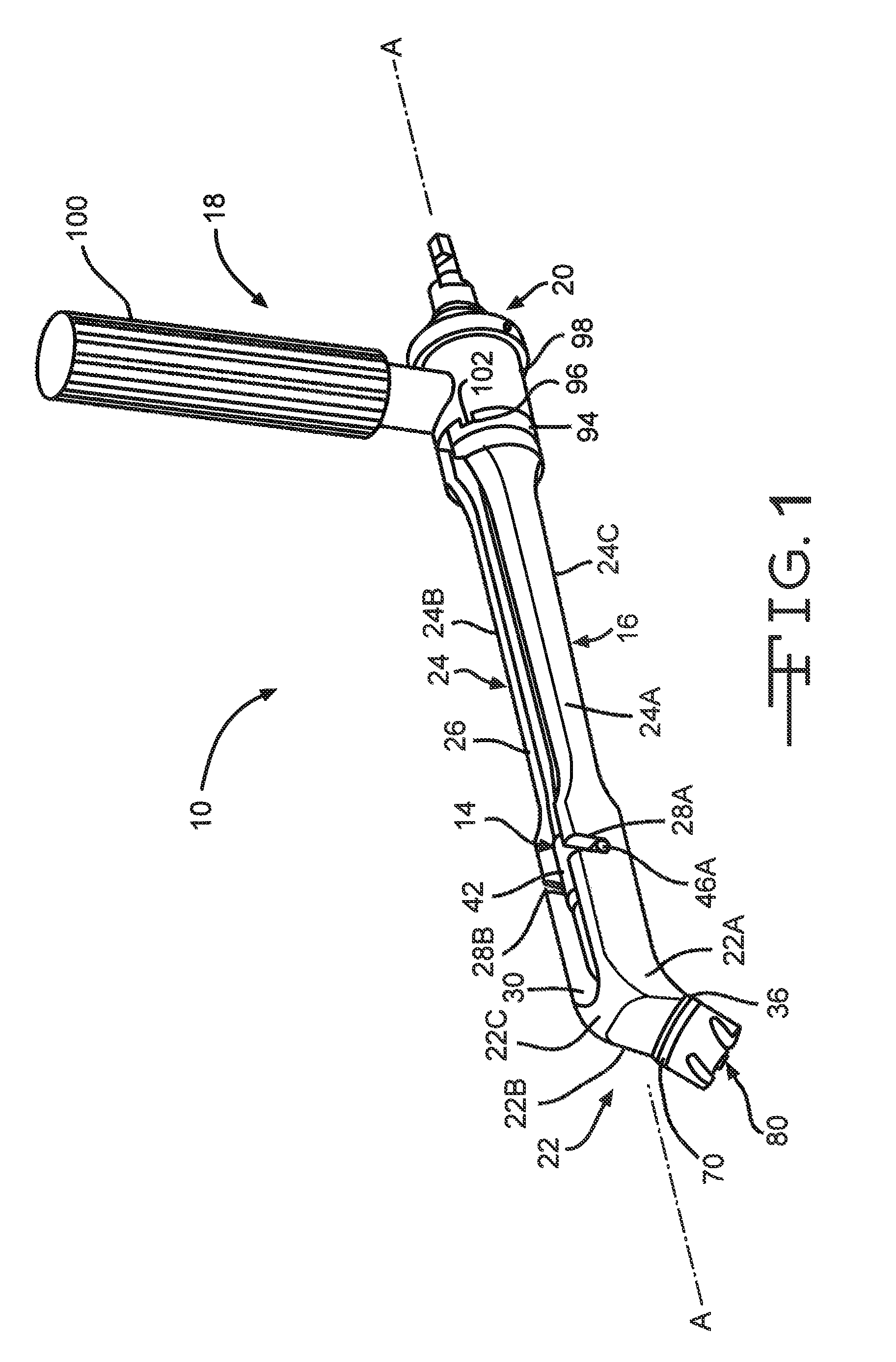
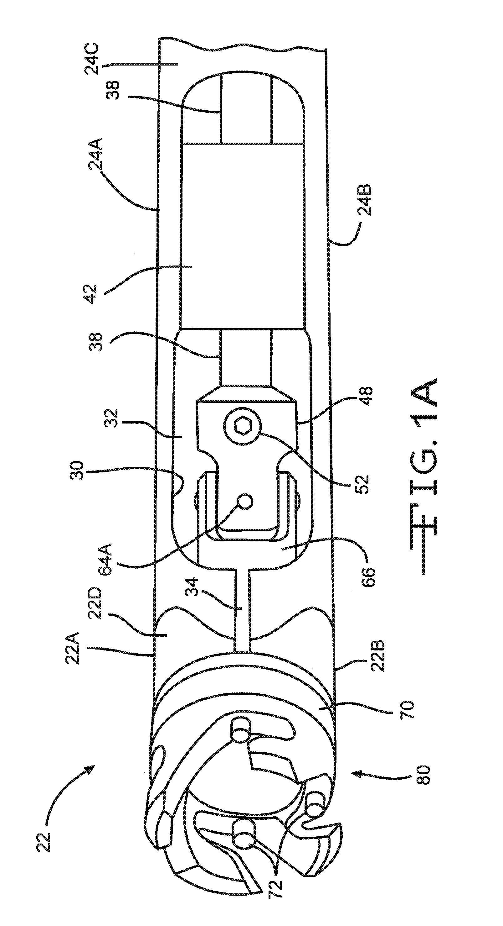
[0031]Turning now to the drawings, FIGS. 1 to 3, 3A to 3F and 4 to 9 illustrate a reamer spindle 10 according to the present invention. The reamer spindle 10 is shown connected to a reamer 12 (FIGS. 4 and 7) for performing a minimally invasive hip replacement surgery. The reamer spindle 10 generally comprises a drive train 14 disposed within a housing 16. A handle assembly 18 is adjustably connected to the housing 16 spaced from the reamer 12.

[0032]The housing 16 had a length that extends from a proximal housing section 20 to a distal neck section 22 with an intermediate housing section 24 there between. The intermediate housing section 24 comprises spaced apart right and left side walls 24A and 24B extending upwardly from a bottom wall 24C to an upper opening 26. This construction provides the intermediate section 24 with a generally U-shaped cross-section perpendicular to a longitudinal axis A-A extending along the proximal and intermediate housing sections 20 and 24, but not alon...


PUM


Abstract

A reamer for use in minimally invasive hip replacement surgical approaches is provided. The reamer spindle includes an elongate housing portion that extends along a first axis and a neck or distal portion that extends along a second axis, wherein the second axis extends at an angle of between about 35 degrees and about 65 degrees relative to the first axis. A reamer head is removably connectable to the distal neck portion and has a surface configured to cut bone.

Description

CROSS REFERENCE TO RELATED APPLICATIONS[0001]This application claims priority to U.S. provisional application. Ser. Nos. 61 / 307,295, filed on Feb. 23, 2010 and 61 / 348,869, filed on May 27, 2010.BACKGROUND OF THE INVENTION[0002]Nearly 200,000 hip replacements are performed each year in the United States and the number is expected to continue to grow as the population ages. The usual reasons for hip replacement are osteoarthritis, rheumatoid arthritis and traumatic arthritis, all of which can cause pain and stiffness that limit mobility and the ability to perform daily living activities. Hip replacement surgery is usually performed when other measures (e.g., physical therapy, medications, and walking aids) are unable to overcome the chronic pain and disability associated with these conditions.[0003]Various techniques are used by orthopedic surgeons to perform hip replacements. These include the following approaches: anterior, antero-lateral, anterior, posterior, and postero-lateral. T...

Claims


Application Information

Patent Timeline
Patent Type & Authority Patents(United States)
IPC IPC(8): A61B17/00
CPCA61B17/1666A61B17/1624
Inventor ROGER, DOUGLAS J.FEHLBAUM, PHILIPPEROSSE, YANN
Owner VIANT AS&O HLDG LLC
Why Eureka
Try Eureka