Insertion device

a technology of insertion device and proximal direction, which is applied in the direction of catheters, sensors, diagnostics, etc., can solve the problems of not being able to simply remove them, not being able to remove them by shifting the insertion device in the proximal direction, and not being able to slit and/or tear open at all or only with great difficulty

Inactive Publication Date: 2008-01-17
BIOTRONIK SE & CO KG
View PDF9 Cites 27 Cited by
  • Summary
  • Abstract
  • Description
  • Claims
  • Application Information

AI Technical Summary

Benefits of technology

[0008]The present invention is based on the object of avoiding the above-mentioned disadvantages of the prior art and providing an insertion device wherein, during the use at the fastening / stimulation location of an electrode line, electrical and physiological body signals may be measured and / or the body tissue may be stimulated.

Problems solved by technology

A known problem of such insertion devices is that it is not possible to remove them simply by pulling them out, because the plug on the proximal end of the electrode line has a larger diameter than the lumen section of an insertion catheter due to standardized dimensions.
Removal by shifting the insertion device in the proximal direction is thus not possible.
This problem is solved according to the prior art in that the cited insertion devices may be slit or torn open from the proximal end to the distal end.
These two cited insertion devices from the prior art have the disadvantage, however, that the slitting and / or tearing open is possible not at all or only with great difficulty.
Such an open, thin-walled metal electrode is very sharp-edged and may thus cause injuries during use.

Method used


Image

  • Insertion device
  • Insertion device

Examples


Embodiment Construction

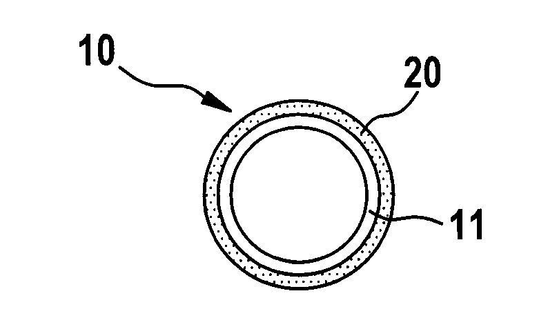
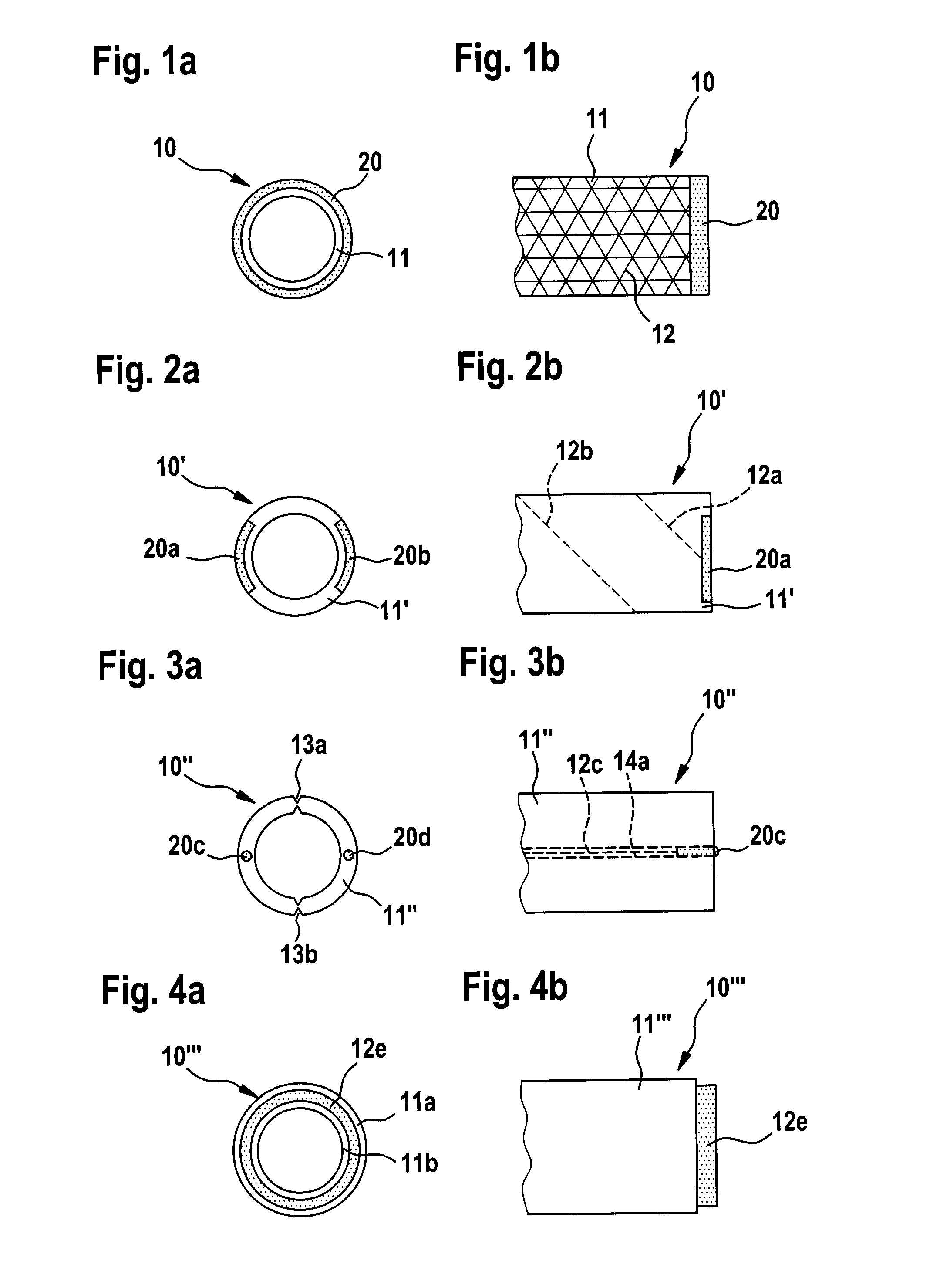
[0025]FIGS. 1a and 1b show a schematic illustration of the distal end of a catheter 10, in which an electrode 20 made of conductive plastic is attached to the distal end of the lumen section 11.

[0026]The electrode 20 is connected to the metallic reinforcement braid 12, which is embedded in the lumen section 11. The reinforcement braid 12 is used, in addition to increasing the rigidity of the lumen section 11, as the electrical connection of the electrode 20 to the proximal area of the insertion catheter (not shown), on which a plug connector of arbitrary, known construction is situated. In the area in which the electrode 20 is seated, the external part of the lumen section is removed by abrasion, for example, so that the reinforcement braid 12 is exposed. The electrode 20 is attached to the distal end of the catheter in such a way that there is an electrical connection between braid and electrode. The electrical connection may be produced by melting a prefinished, annular electrode ...


PUM

PropertyMeasurementUnit
flexibleaaaaaaaaaa
electrically conductiveaaaaaaaaaa
lengthaaaaaaaaaa

Abstract

An insertion device (10), by which a medical instrument or an electrode line or a guide wire or a medical therapeutic agent may be inserted into a body cavity, comprises a lumen section (11) manufactured from a flexible plastic material, having a longitudinal axis, a proximal end and a distal end, and a distal end area enclosing the distal end, at least one electrically conductive means (20) in the distal end area to sense physiological signals or stimulate the surrounding body tissue suitably, as well as at least one conductor, which extends from the proximal end to the distal end and is capable of conducting physiological signals to the proximal end and/or stimulation pulses to the distal end. The at least one electrically conductive means is produced from a flexible, not exclusively metallic, electrically conductive substrate.

Description

FIELD OF THE INVENTION [0001]The present invention relates to an insertion device for inserting a medical instrument, an electrode line, a guide wire, or a medical therapeutic agent into the body cavity of a human or animal body.BACKGROUND OF THE INVENTION [0002]The foregoing insertion devices are known, for example, as insertion catheters and are used for placing a cardiac electrode line or a guide wire in the interior of the heart, in a coronary artery of the heart—such as the coronary sinus—or in a blood vessel connected adjoining the heart—such as the vena cava. Cardiac electrode lines are lines which produce an electrical contact between an electrically active implant such as a cardiac pacemaker or an implantable cardioverter / defibrillator (ICD) and an electrode head electrically connected to the heart, to stimulate the heart or record physiological measured values. Special embodiments of such electrodes, so-called “over the wire” electrodes, may be placed with the aid of a gui...

Claims


Application Information

Patent Timeline
Patent Type & Authority Applications(United States)
IPC IPC(8): A61M25/14A61B5/00A61N1/00
CPCA61M25/0045A61N1/056A61M25/0668A61M25/0662
Inventor GEISTERT, WOLFGANGFLACH, ERHARD
Owner BIOTRONIK SE & CO KG
Why Eureka
Try Eureka