Flow-directed catheter guide with variable rigidity shaft

a catheter guide and variable rigidity technology, applied in the field of catheter guides, can solve the problems of incompatibility between two requirements, insufficient rigidity of flexible catheter guides, and extremely problematic, and achieve the effect of facilitating the withdrawal of catheter guides

Inactive Publication Date: 2010-01-14
VASCULAR PATHWAYS
View PDF22 Cites 29 Cited by
  • Summary
  • Abstract
  • Description
  • Claims
  • Application Information

AI Technical Summary

Benefits of technology

[0009]In keeping with the foregoing discussion, the present invention provides a catheter guide with a variable rigidity shaft. The variable rigidity shaft of the catheter guide can be selectively changed between a flexible state and a rigid state. The catheter guide can be inserted into a patient's vein or artery with the variable rigidity shaft in a flexible state to avoid trauma to the vessel walls. Once the catheter guide has been inserted, the variable rigidity shaft can be converted to the rigid state to provide a firm support for insertion of a catheter coaxially over the catheter guide. After the catheter has been inserted, the variable rigidity shaft is allowed to return to the flexible state to facilitate withdrawal of the catheter guide.

Problems solved by technology

These two requirements can sometimes be incompatible, particularly in difficult to catheterize vessels.
However, such a flexible catheter guide may not be rigid enough to guide the catheter through the tissue and any sharp bends, tortuosity or narrowing in the vessel without pulling back or kinking.
This can be extremely problematic in cases where successful catheterization is critical to the survival of the patient.
However, it necessarily involves a compromise in the characteristics of the catheter guide that will not be adequate in all cases, particularly in difficult cases like those described above.
However, the instructions for use provided with these products warn against advancing the movable core again once the guidewire has been inserted into the patient because of the danger that the core may exit the guidewire between the coils of the spring and damage or pierce the vessel wall.
For this reason, such movable core guidewires do not provide an adequate means for changing a catheter guide from flexible to stiff after it has been inserted into the patient's blood vessel.
These flow-directed catheters however are not suitable as catheter guides.

Method used


Image

  • Flow-directed catheter guide with variable rigidity shaft
  • Flow-directed catheter guide with variable rigidity shaft
  • Flow-directed catheter guide with variable rigidity shaft

Examples


Embodiment Construction

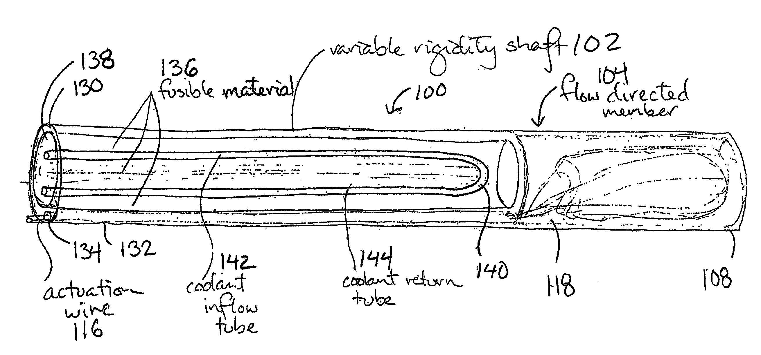
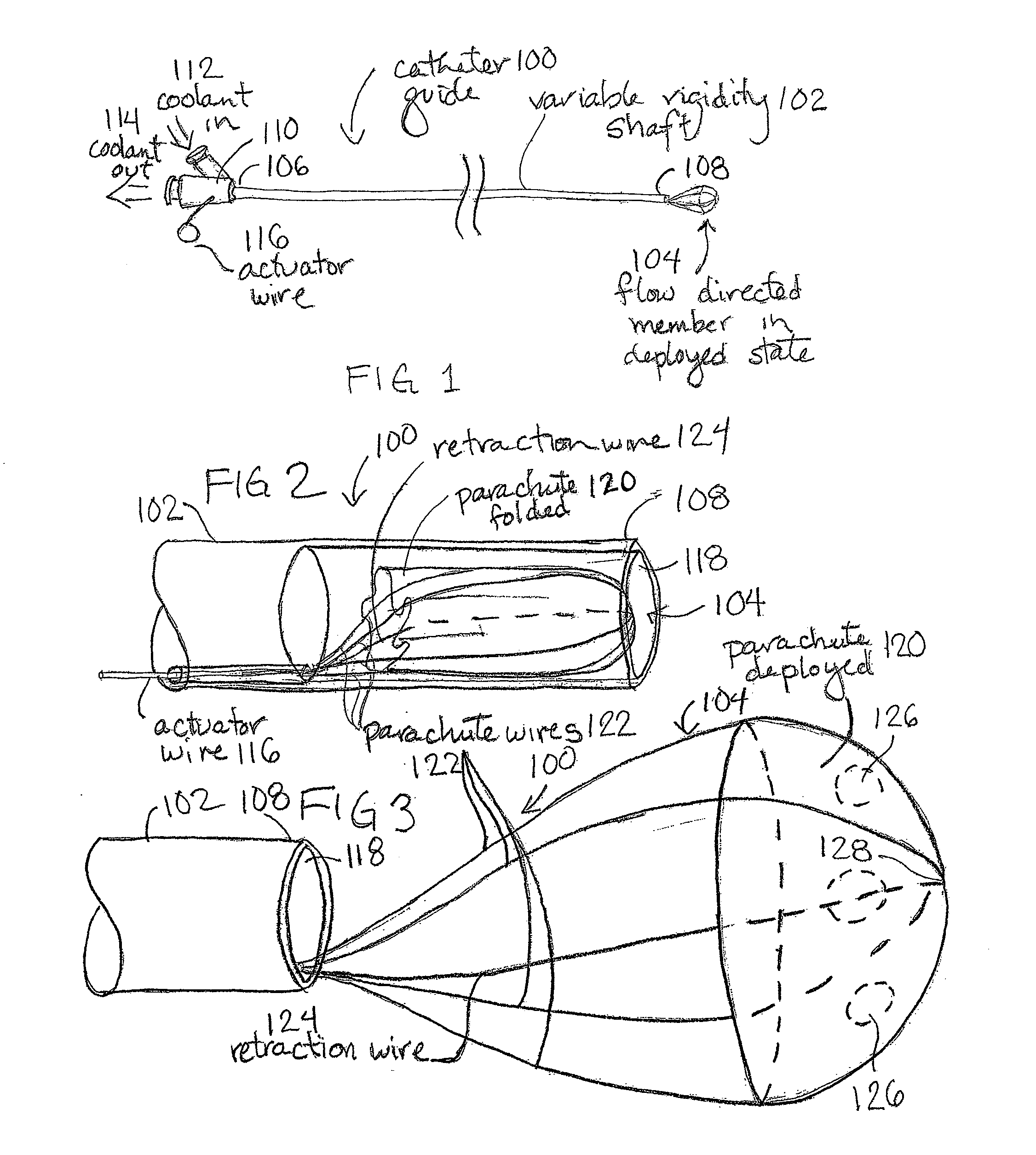
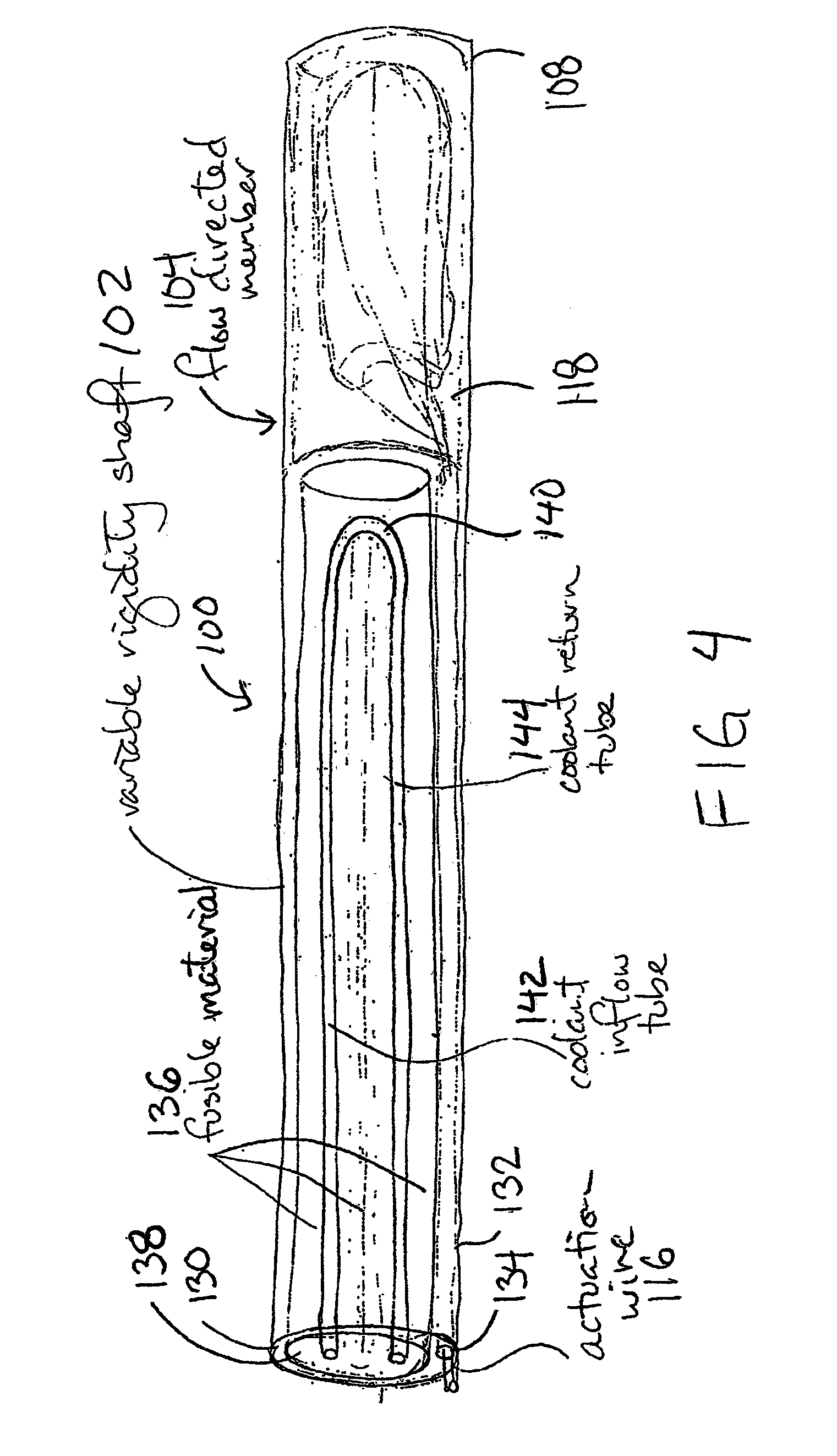
[0020]FIG. 1 shows a flow-directed catheter guide 100 with a variable rigidity shaft 102 constructed according to the present invention. The catheter guide 100 has an elongated shaft 102 with a proximal end 106 and a distal end 108. At least a distal portion of the catheter guide shaft 102 is constructed as a variable rigidity shaft. The distal end 108 of the catheter guide 100 has a flow-directed member 104, which is shown in a deployed state. The proximal end 106 of the catheter guide 100 has a proximal fitting 110 with connections for inflow 112 and outflow 114 of coolant and an actuation wire 116 or the like for selectively actuating the flow-directed member 104. Optionally, the proximal fitting 110 may be removable from the elongated shaft 102.

[0021]Alternatively, the flow-directed member 104 described herein may be mounted on a catheter guide or catheter of more conventional construction. For example, the flow-directed member 104 may be mounted to the distal end of a conventio...


PUM


Abstract

A flow-directed catheter guide includes a selectively deployable flow-directed member and a variable rigidity shaft. The variable rigidity shaft can be selectively changed between a flexible state and a rigid state. The flow-directed member can be deployed to direct the distal end of the catheter guide downstream following the blood flow in the vessel.

Description

CROSS REFERENCE TO RELATED APPLICATIONS[0001]This application is a continuation of U.S. patent application Ser. No. 10 / 210,736, filed Jul. 31, 2002 titled “FLOW DIRECTED CATHETER WITH VARIABLE RIGIDITY SHAFT”, which claims the benefit under 35 U.S.C. 119 of U.S. Provisional Patent Application No. 60 / 309,268 filed Jul. 31, 2001, which is hereby incorporated by reference in its entirety.INCORPORATION BY REFERENCE[0002]All publications and patent applications mentioned in this specification are herein incorporated by reference to the same extent as if each individual publication or patent application was specifically and individually indicated to be incorporated by reference.FIELD OF THE INVENTION[0003]The present invention relates generally to catheters and catheter guides. More particularly, it relates to a flow-directed catheter guide with a variable rigidity shaft to assist in insertion and guidance of a vascular catheter.BACKGROUND OF THE INVENTION[0004]The Seldinger technique is ...

Claims


Application Information

Patent Timeline
Patent Type & Authority Applications(United States)
IPC IPC(8): A61M25/09A61M29/00A61M25/00A61M25/01
CPCA61M25/0054A61M2240/00A61M25/0125
Inventor BELSON, AMIR
Owner VASCULAR PATHWAYS
Why Eureka
Try Eureka