Composite bin for powder or particle material

a technology of powder or particle material and composite bin, which is applied in the field of composite bin, can solve the problems of material leakage, material leakage, and large volume of inner accommodating volume, and achieve the effect of increasing material efficiency and large inner accommodating volum

Inactive Publication Date: 2013-07-09
PU XIAO +1
View PDF26 Cites 6 Cited by
  • Summary
  • Abstract
  • Description
  • Claims
  • Application Information

AI Technical Summary

Benefits of technology

[0020]By adopting the structure of the composite bin of the invention, a larger inner accommodating volume can be obtained by using the same amount of the consumed material for the outer surface of the composite bin, and the efficiency of the material is thus increased.

Problems solved by technology

Thus, there are lots of cavities, which can not be used for accommodating the material, formed between the outer housing part and the sliding plates as well as the conical bottom part of the inner chamber.
Likewise, there are lots of cavities, which can not be used for accommodating the material, formed between the outer housing part and the sliding plates of the inner chamber.
Due to the presence of such cavities, the material would leak to said cavities once cracks appear in walls of the inner chamber.
Consequently, the inner chamber has to be emptied and the leaked material has to be removed during maintenance, and the cracks could be welded only from the inner side of the inner chamber, such that the quality of welding can not be guaranteed and the cost of maintenance is high.
During manufacturing, extra materials for forming the surface of the bin should be needed to form this concave part, which could provide no contribution to the inner volume of the composite bin, and this in turn causes a waste of the surface material.

Method used


Image

  • Composite bin for powder or particle material
  • Composite bin for powder or particle material
  • Composite bin for powder or particle material

Examples


first embodiment

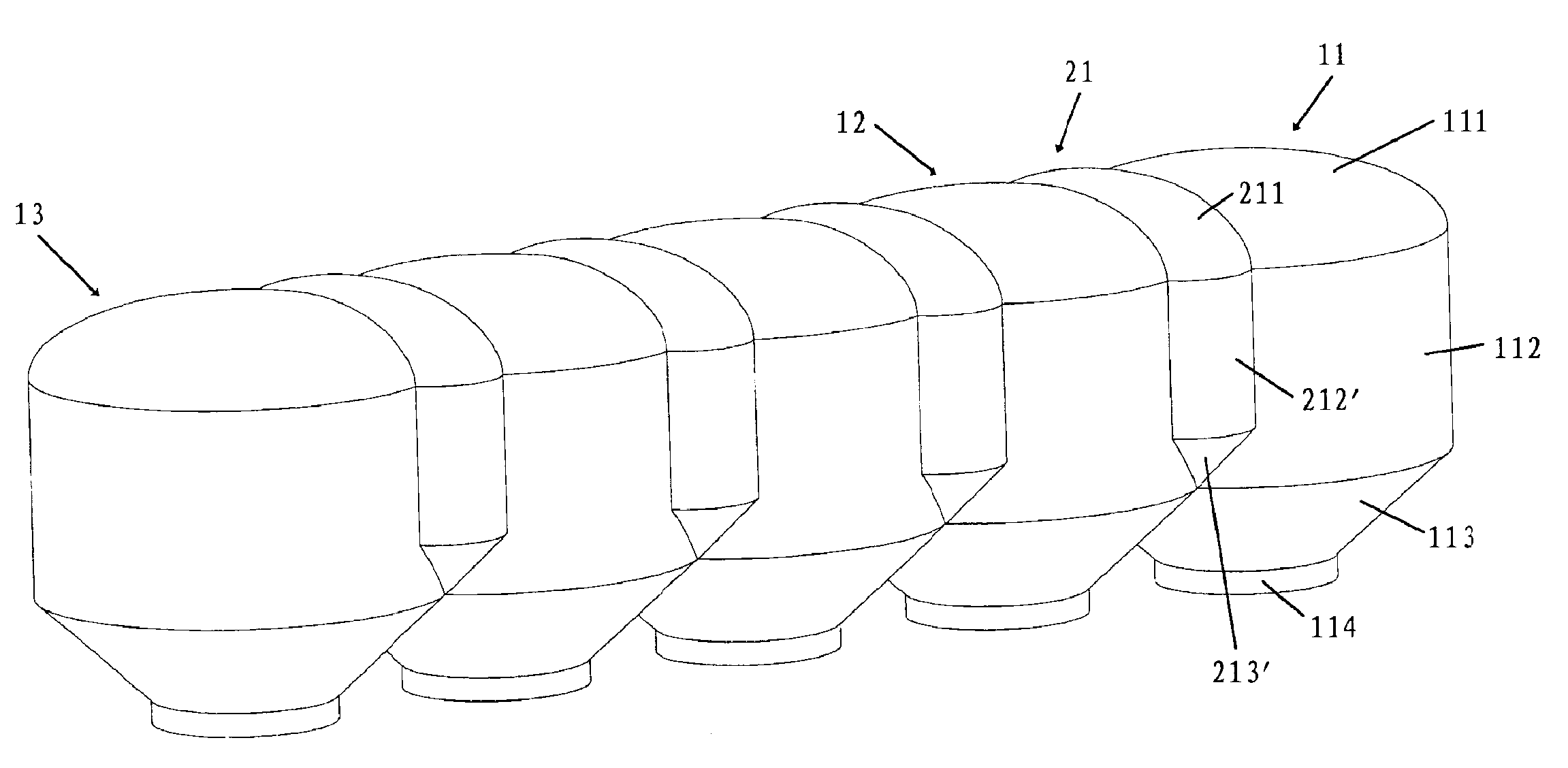
[0034]FIG. 5 is a schematic perspective view of the composite bin according to the invention. FIG. 6 is a cross section view of the composite bin of FIG. 5 taken along the horizontal plane. As shown in the figures, the composite bin of the invention includes multiple main bin units vertically formed and arranged in a line, including terminal main bin units 11, 13 and intermediate main bin units 12. The difference between the terminal main bin unit and the intermediate main bin unit only lies in that the terminal main bin unit is connected to another main bin unit at only one side, while the intermediate main bin unit is connected to other main bin units at both sides. Although five main bin units are shown in the figures, those skilled in the art could understand that it is just an explanatory example and the actual number of the main bin units should not be limited to 5 but can be set otherwise depending on the specific requirement to meet.

[0035]The main bin units will be described...

fourth embodiment

[0037]In the embodiment shown in FIG. 5, the heights of the main side walls are the same, while the height of each supplementary side walls 212, 212′ is smaller than that of the main side wall 112 of the main bin unit, with each supplementary side walls extending from the top downward so as to cover only a part of the height of said main side wall, such as a half. The supplementary bottom parts 213, 213′ gradually extend from the lower edges of the supplementary side walls 212, 212′ to the plane of the connecting seams where the main side walls 112 and the main bottom parts of the main bin unit intersect with each other, and are connected to the adjacent main bin units, so as to make it possible to direct the downward movement of the material accommodated in the supplementary bin units and finally discharge the material via the bottom parts of the adjacent main bin units. In the fourth embodiment shown in FIG. 10 where the heights of the main side walls are different, the heights of...

second embodiment

[0039]Likewise, in the above case as shown in the second embodiment in FIG. 8, covering board 215, 215′, extending downwardly from the outer surface of the cylindrical side walls 212, 212, can be provided outside the supplementary bottom parts 213, 213′, to cover the supplementary bottom parts from the outside and thus achieve an esthetic appearance of the composite bin.


PUM


Abstract

A sealed composite bin for accommodating and delivering powder or particle material has multiple main bin units (11-13) arranged vertically and connected with each other, each including an arched main top part (111), a cylindrical main side wall (112) and a conical main bottom part (113). The radius of each main side wall is approximately the same, the in-line arrangement of the multiple main bin units (11-13) make the distance between the axes of the adjacent main bin units less than the sum of the radii of the two corresponding main side walls, and the multiple main bin units are communicated with each other. A supplementary bin unit (21) is provided between the adjacent main bin units, and the supplementary bin unit (21) includes a supplementary top part (211) connected to the top parts of the adjacent main bin units and cylindrical supplementary side walls (212,212′) connected to the side walls of the adjacent main bin units. The structure of the composite bin of the invention can obtain more inner volume by using the same amount of material for the exterior surface, and hence improves the using efficiency of the material.

Description

CROSS REFERENCE TO RELATED APPLICATIONS[0001]This is the National Stage of International Application PCT / CN2007 / 003381, with an international filing date of Nov. 29, 2007.TECHNICAL FIELD[0002]The invention relates to an apparatus for accommodating and delivering powder or particle material, and particularly to a composite bin used for accommodating and delivering powder or particle material and installed on a transporting vehicle.BACKGROUND[0003]A conventional bin used for powder or particle material and installed on transporting vehicle is in a form of horizontally arranged cylindrical tank or horizontally arranged double-conical-tank, as shown in FIGS. 1 and 2. FIG. 1 shows a conventional bin in the form of a horizontally arranged cylindrical tank, including cylindrical outer housing part and multiple inner chambers disposed inside said housing part and communicated with each other to accommodate the material therein. A discharging port is disposed in the bottom part of each inner...

Claims


Application Information

Patent Timeline
Patent Type & Authority Patents(United States)
IPC IPC(8): B65D88/00
CPCB60P3/2205B65D88/26B65D88/32
Inventor PU, XIAOXIAO, HUI
Owner PU XIAO
Why Eureka
Try Eureka