Passive ankle-foot prosthesis and orthosis capable of automatic adaptation to sloped walking surfaces and method of use

a passive, walking surface technology, applied in the field of improved ankle foot prosthetics and orthotic systems, can solve the problems problems that can arise, and many currently available ankle-foot mechanisms that do not allow ankle motion, so as to prevent or reduce the likelihood of compromising user's balan

Active Publication Date: 2013-07-09
REHABILITATION INST OF CHICAGO +2
View PDF29 Cites 39 Cited by
  • Summary
  • Abstract
  • Description
  • Claims
  • Application Information

AI Technical Summary

Benefits of technology

[0008]The invention provides prosthetic and orthotic ankle-foot systems. The systems can be used by a human subject as a prosthesis or an orthosis to assist the user's gait and to prevent or reduce the likelihood of compromising the user's balance.
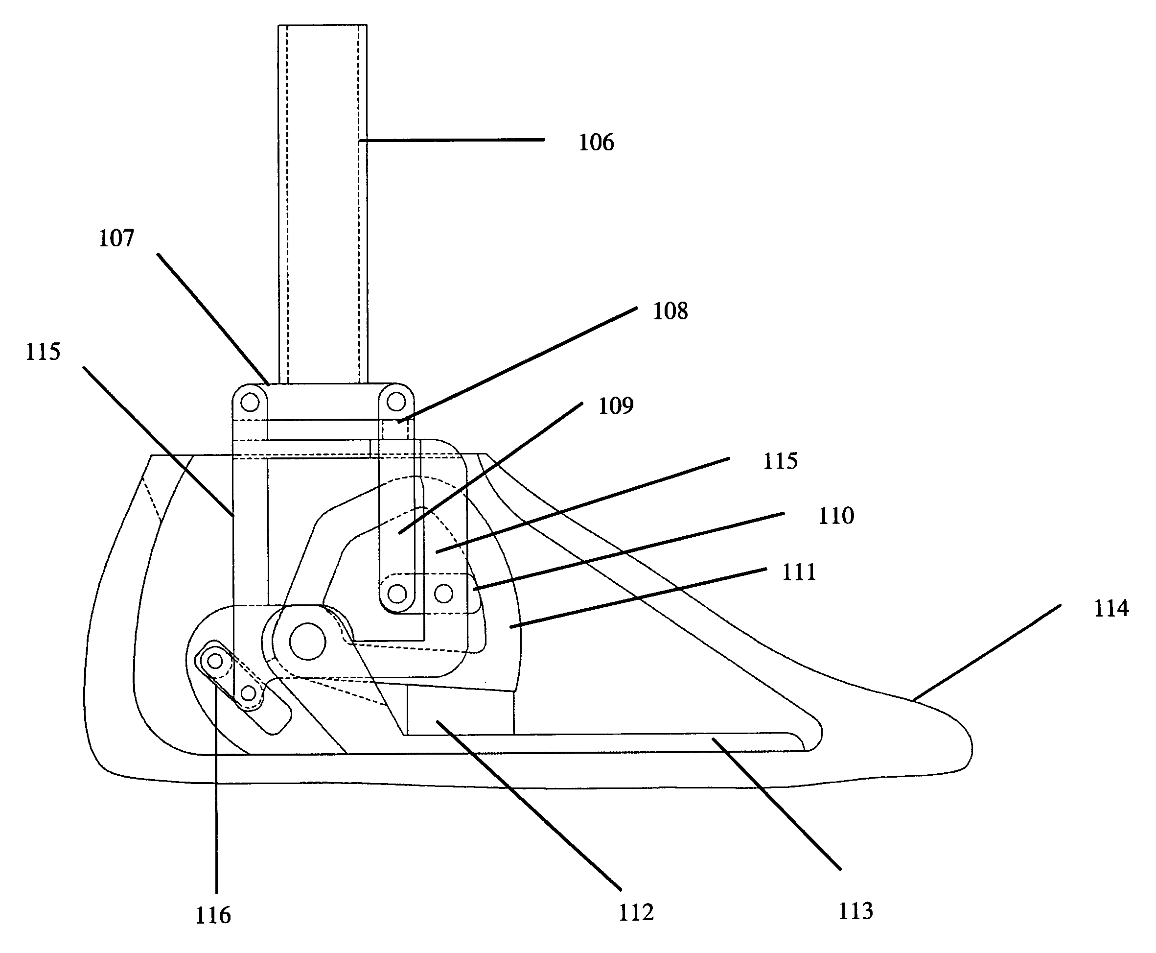
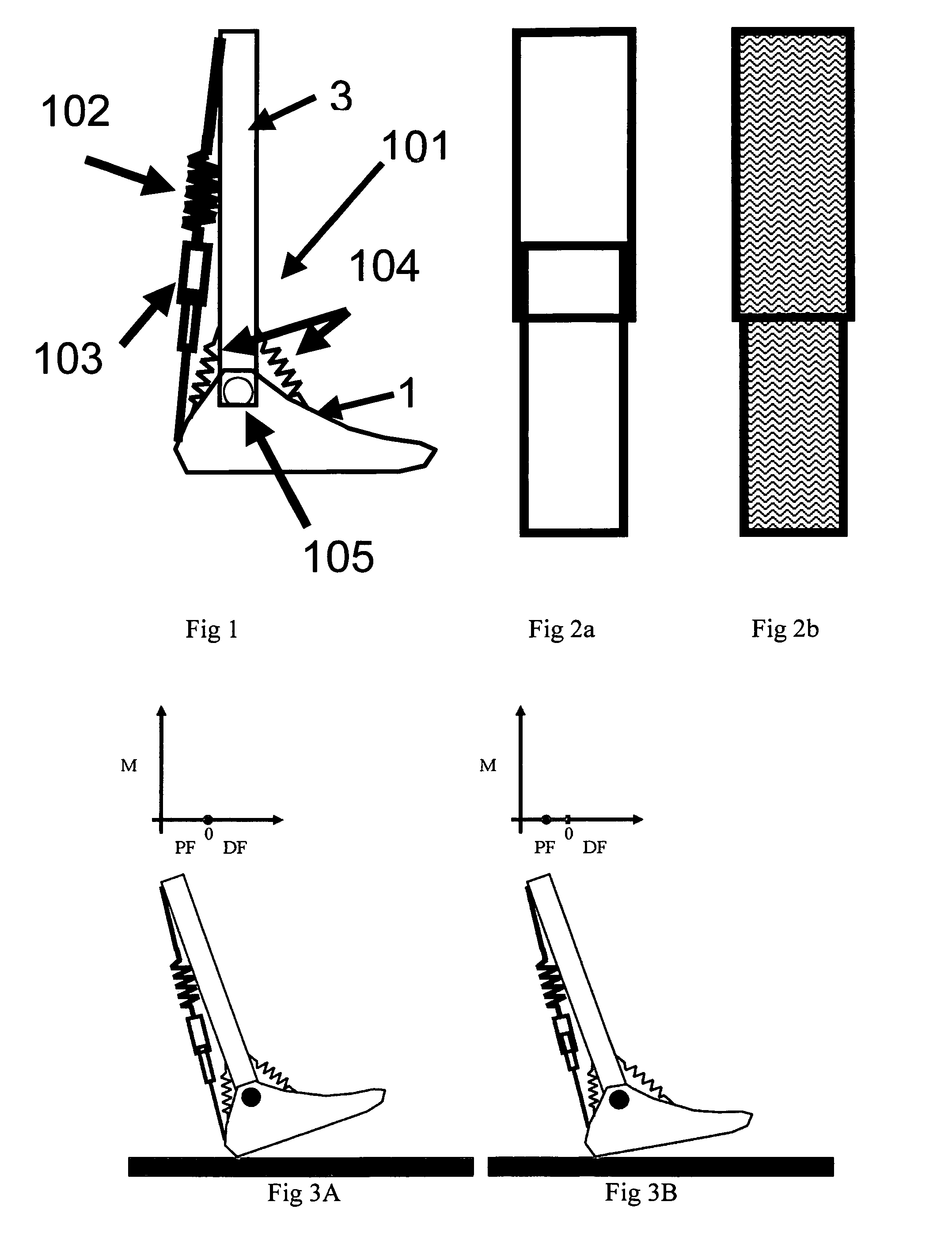
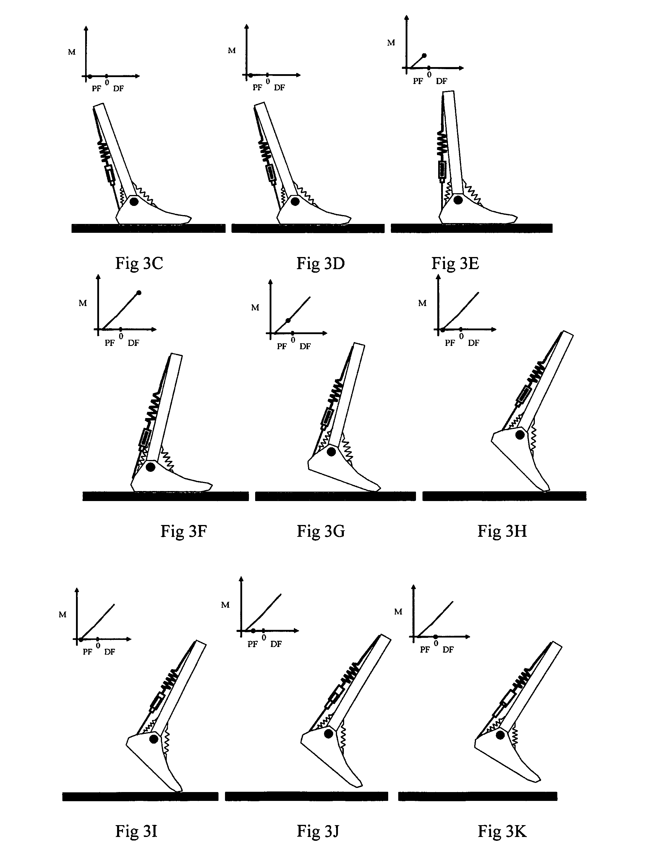
[0009]In one embodiment the invention provides a self-adapting prosthetic system, the self-adapting prosthetic system comprising a foot shell, an improved passive adaptive ankle-foot prosthesis, and means for attachment to a leg, the ankle foot prosthesis comprising a footplate, an ankle system, the ankle system comprising a housing, a first cam, a second cam, a bracket, wherein the housing and the bracket are fixedly attached to the means for attachment to the leg, wherein the bracket is fixedly attached to the first cam, wherein the first cam is in movable contact with a part of the second cam and the first cam and second cam comprise a cam clutch system, and wherein the footplate comprises an anterior portion and a posterior portion and further comprising an essentially horizontal plantar member, a torsion means, and an essentially vertical member, the vertical member being perpendicular to the horizontal plantar member and operatively attached to the posterior portion of the footplate, the vertical member further comprising an aperture, the aperture shaped and adapted to confine at least one neutralizing element and a spacer, the neutralizing element being operatively connected to the spacer, wherein the spacer is axially connected to the housing, wherein the housing is axially connected to the vertical member of the footplate, and wherein the second cam is axially connected to the vertical member of the footplate and wherein the torsion means is shaped and adapted for confined placement between the second cam and the horizontal plantar member, and wherein the improved passive adaptive ankle-foot prosthesis is shaped and adapted for placement within the foot shell and wherein the foot shell comprises, in part, a flexible material. In a preferred embodiment, wherein the torsion means is selected from the group consisting of a spring, a tunable spring, a clockwork spring, a piston, a damper, a bumper, and an elastomeric material. In another preferred embodiment the neutralizing element and the cam clutch are in-line. In yet another preferred embodiment, the second cam comprises an external surface and an internal surface. In a more preferred embodiment, the first cam is in movable contact with the internal surface of the second cam. In a most preferred embodiment the range of movable contact of the first cam in contact with the second cam is not greater than 95°. In another most preferred embodiment, the ankle system has a plantarflexion-dorsiflexion range of from between 80° plantarflexion to about 45° dorsiflexion. In another embodiment the ankle system allows a user to emulate normal gait. In an alternative embodiment, the ankle system allows a user to approximately emulate normal gait.
[0011]In another embodiment the invention provides a self-adapting orthotic system, the self-adapting orthotic system comprising a footplate, an improved passive adaptive ankle system, and means for attachment to an ankle, the ankle system comprising the footplate, means for attaching to the means for attachment to an ankle, a housing, a first cam, a second cam, a bracket, wherein the housing and the bracket are fixedly attached to the means for attachment to the ankle, wherein the bracket is fixedly attached to the first cam, wherein the first cam is in movable contact with a part of the second cam and the first cam and second cam comprise a cam clutch system, and wherein the footplate comprises an anterior portion and a posterior portion and further comprising an essentially horizontal plantar member, a torsion means, and an essentially vertical member, the vertical member being perpendicular to the horizontal plantar member and operatively attached to the posterior portion of the footplate, the vertical member further comprising an aperture, the aperture shaped and adapted to confine at least one neutralizing element and a spacer, the neutralizing element being operatively connected to the spacer, wherein the spacer is axially connected to the housing, wherein the housing is axially connected to the vertical member of the footplate, and wherein the second cam is axially connected to the vertical member of the footplate and wherein the torsion means is shaped and adapted for confined placement between the second cam and the horizontal plantar member, and wherein the improved passive adaptive ankle-foot orthosis is shaped and adapted for placement on at least one side of the biological ankle of the user or individual. In a preferred embodiment, wherein the torsion means is selected from the group consisting of a spring, a tunable spring, a clockwork spring, a piston, a damper, a bumper, and an elastomeric material. In another preferred embodiment the neutralizing element and the cam clutch are in-line. In yet another preferred embodiment, the second cam comprises an external surface and an internal surface. In a more preferred embodiment, the first cam is in movable contact with the internal surface of the second cam. In a most preferred embodiment the range of movable contact of the first cam in contact with the second cam is not greater than 95°. In another most preferred embodiment, the ankle system has a plantarflexion-dorsiflexion range of from between 80° plantarflexion to about 45° dorsiflexion. In another embodiment the ankle system allows a user to emulate normal gait. In an alternative embodiment, the ankle system allows a user to approximately emulate normal gait.

Problems solved by technology

Many currently available prosthetic and orthotic ankle-foot mechanisms do not allow ankle motion.
However, problems can arise when walking on different terrain or when using shoes of different heel height.
However, this is not a simple task and one that does not happen automatically.
However, Koniuk's design does not appear to have energy storage and release properties, utilizes more sensing devices than the proposed design, and does not appear to give plantarflexion at late stance.
Current prosthetic ankle-foot mechanisms cannot automatically adapt to these conditions.

Method used


Image

  • Passive ankle-foot prosthesis and orthosis capable of automatic adaptation to sloped walking surfaces and method of use
  • Passive ankle-foot prosthesis and orthosis capable of automatic adaptation to sloped walking surfaces and method of use
  • Passive ankle-foot prosthesis and orthosis capable of automatic adaptation to sloped walking surfaces and method of use

Examples


example i

Use of Weight-Activation to Control the Ankle Mechanism

[0094]Engagement can be set to occur upon loading of the device by the user's weight. In this case, a mechanism is in place that engages the triceps surae torsional means after a sufficient amount of body weight has been applied to the system. Upon unloading of the device, the engagement reverses (that is the triceps surae spring is disengaged from the rest of the system). Examples of this type of engagement are shown in FIGS. 9, 34, 35, 36, 37, 38, 39, and 40.

example ii

Use of Potentiometers or Encoders to Control Locking-Unlocking Mechanisms

[0095]The projected ankle motion of this device is shown in FIG. 33. The potentiometers or encoders measure these angles during use of the device. In early stance, the locking mechanism may be unlocked. When the rotational sensor indicated that a minimum dorsiflexion angle is reached (at time 1), the system will signal to engage the locking mechanism. This mechanism remains engaged until this angle is approached at the end of stance phase (at time 2), at which time the system unlocks and allows the neutralizing springs to bring the ankle back to neutral for swing phase.

example iii

Use of Forefoot Pressure Sensors to Control Locking-Unlocking Mechanisms

[0096]An alternative way to control the locking and unlocking mechanism is to use a forefoot pressure sensor. In early stance, the ankle plantarflexes until the forefoot contacts the walking surface. At this first contact with the forefoot pressure sensor, the locking mechanism may be engaged. Forefoot contact remains until the toe comes off of the ground at the end of stance. At this time, the pressure goes to zero and the locking mechanism could be unlocked, allowing the neutralizing springs to bring the ankle back to neutral for swing phase.


PUM


Abstract

The present invention relates to an improved system for use in rehabilitation and / or physical therapy for the treatment of injury or disease to the lower limbs or extremities. The system can enable an amputee to proceed over any inclined or declined surface without overbalancing. The system is mechanically passive in that it does not utilize motors, force generating devices, batteries, or powered sources that may add undesirable weight or mass and that may require recharging. In particular the system is self-adapting to adjust the torque moment depending upon the motion, the extent of inclination, and the surface topography. An additional advantage of the improvement is that the system can be light and may also be simple to manufacture.

Description

[0001]The present application claims priority to U.S. Provisional Patent Application Ser. No. 61 / 342,281 entitled “Improvements to Passive Ankle-Foot Prosthesis Capable of Automatic Adaptation to Sloped Walking Surfaces and Methods of Use”, filed 12 Apr., 2010, which is herein incorporated by reference in its entirety for all purposes. This application is also related to International Patent Application Serial No. PCT / US2007 / 022208, filed 17 Oct., 2007, U.S. patent application Ser. No. 12 / 311,818, filed 13 Apr., 2009, and U.S. Provisional patent application Ser. No. 60 / 852,174, filed 17 Oct. 2006.[0002]This invention was made with government support under United States Department of Veterans Affairs' grant numbers A6567R and A6565R. The United States government has certain rights in the invention.TECHNICAL FIELD[0003]The inventions relate to improved ankle-foot prosthetic and orthotic systems and methods of use. In particular the prosthetic or orthotic systems comprise an ankle unit...

Claims


Application Information

Patent Timeline
Patent Type & Authority Patents(United States)
IPC IPC(8): A61F2/66
CPCA61F2/6607A61F2002/5072A61F2002/6845
Inventor HANSEN, ANDREW H.SENSINGER, JONATHON W.
Owner REHABILITATION INST OF CHICAGO
Why Eureka
Try Eureka