
Automated emergency power supply test using variable load bank stages

a power supply and variable load technology, applied in power supply testing, instruments, electric devices, etc., can solve the problems of insufficient monitoring of the terminal voltage of the battery, inability to detect manual data collection methods, subtle and gradual, etc., to increase the overall reliability of the eps system, reduce the burden of staff, and increase reliability

Active Publication Date: 2013-07-09
SCHNEIDER ELECTRIC USA INC
View PDF2 Cites 14 Cited by
  • Summary
  • Abstract
  • Description
  • Claims
  • Application Information

AI Technical Summary

Benefits of technology

[0007]Automated EPSS testing increases reliability due to the accurate monitoring and recording of test parameters, it provides traceability in case of unanticipated problems with the EPS system or litigation, and it helps to reduce the staffing burden for such tests, among other advantages. A goal of automated EPSS testing is to increase the overall reliability of the EPS system and to reduce the odds of failure under emergency situations.
[0008]Automated testing and monitoring helps identify EPSS problems during testing rather than during emergency situations. By pointing out problem areas during tests, the EPS system's overall mean time between failures (MTBF) can be improved. It is important to ensure that any testing or EPSS operation is performed within the intended operating parameters. This can be achieved by continuously monitoring the EPS system and electronically measuring and recording all relevant automatic transfer switch (ATS), engine-generator (genset) and related parameters, such as transfer times, engine loading, engine temperature, exhaust gas temperature, and oil pressure.
[0011]Also, by continuously monitoring the EPS system, alarms can be triggered if the EPS system is operated outside its intended parameters for prolonged periods of time to avoid reliability threats such as wet stacking, clogged fuel filters or tired batteries. Further, transfer switches and circuit breakers require exercising and mechanical maintenance at regular intervals to assure they operate as intended. Having precise electronic records of the exact times when these devices have been exercised makes it easy to determine when they are due for their next exercising operation.
[0012]In the US, for example, hospitals are required to follow NFPA 99 and 110, which prescribe that EPS systems have to be tested at least 12 times a year, every 20 to 40 days, for a minimum of 30 minutes at the manufacturer's recommended exhaust gas temperature or at a minimum load of 30% of the genset's rating. An automated EPSS test solution makes it straightforward to prove conformance to legislative test procedures and requirements.
[0013]In Europe, IEC 60364-7-710 prescribes that changeover devices are to be functionally tested every 12 months. Genset combustion engines are to be tested monthly until rated running temperature is achieved with an additional 60-minute annual endurance test. In all cases at least 50% to 100% of the rated power shall be applied. At the same time, hospitals are required to keep precise maintenance and test records for presentation to regulating authorities, or for traceability to determine what happened in the system after improperly functioning or system failure. In the case of system failure, despite proper testing, it is important to have access to detailed electronic data which facilitates sequence of event or cause and effect studies.

Problems solved by technology

Simply checking the terminal voltage of the batteries is not sufficient to monitor their ability to deliver adequate cranking power.
Or, an abnormal drop in battery voltage during engine cranking may indicate that it is time to replace the batteries.
Some of these trends may be very subtle and gradual, and often cannot be detected by manual data collection methods.

Method used


Image

  • Automated emergency power supply test using variable load bank stages
  • Automated emergency power supply test using variable load bank stages
  • Automated emergency power supply test using variable load bank stages

Examples


Embodiment Construction

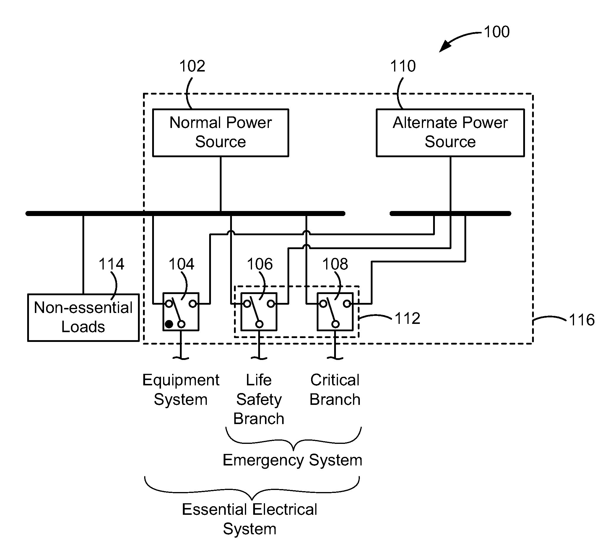
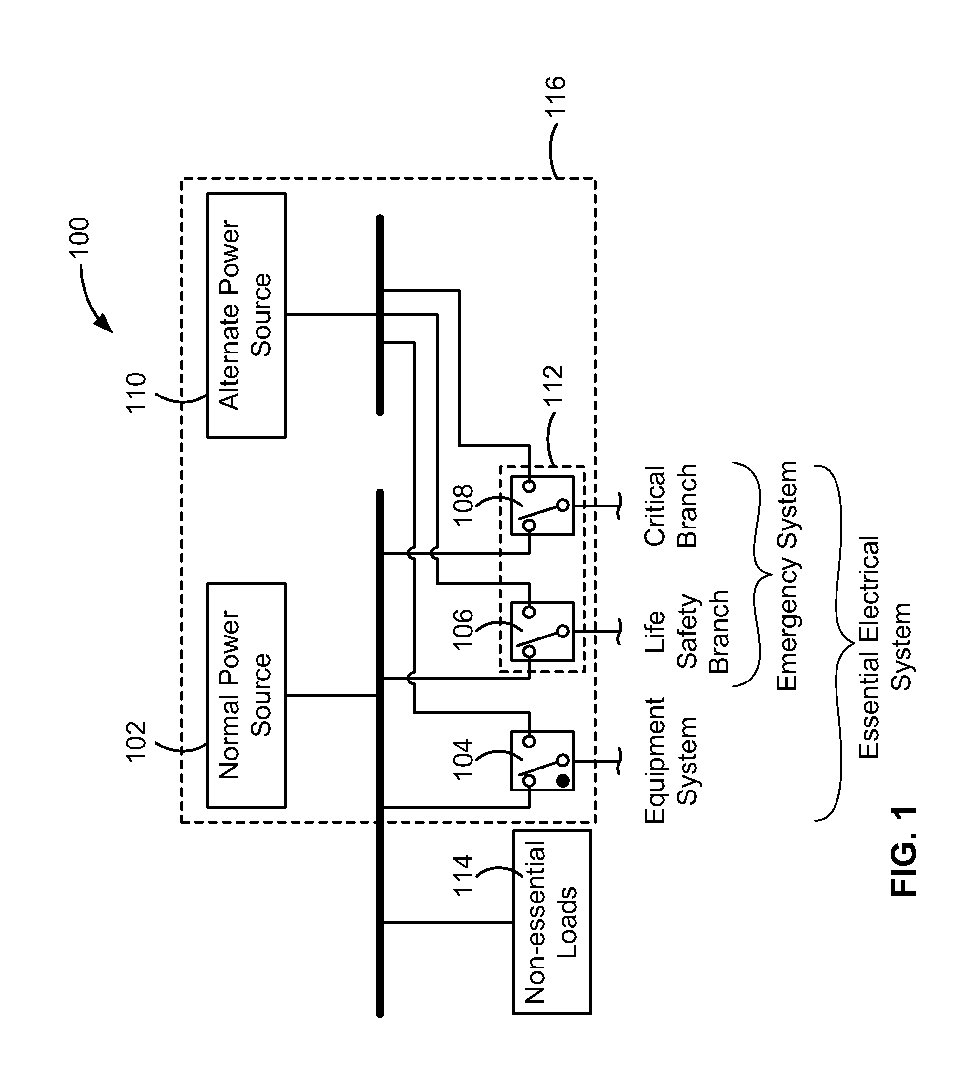
[0108]FIG. 1 is a functional block diagram of an example electrical system 100 that normally supplies electrical current to electrical loads within a facility or building, such as a hospital or healthcare facility, from a normal power source 102. When power supplied by the normal power source 102, such as a main utility power source, is interrupted, automatic switching equipment 104, 106, 108 automatically switches power supplied by the normal power source 102 to an alternate power source 110, such as a generator or genset, as that term is understood by those skilled in the art of power systems, or a direct current (DC) power source such as a battery. In the case of a hospital, the electrical system 100 can include an emergency system112 that supplies power to essential loads within the hospital that are supplied by life safety or critical branch circuits. Non-essential loads 114 in the hospital remain unpowered during a power outage from the normal power source 102. Within the esse...


PUM


Abstract

An automated emergency power supply system (EPSS) and testing solution that records generator load values and engine exhaust temperature values to evaluate whether an EPSS test satisfies legislated test criteria. The EPSS test is carried out under software control, which initiates a test by instructing an automatic transfer switch (ATS) to change its status to a test status, causing the essential loads to be powered by a generator instead of a main utility power source. Power monitors record the ATS and generator status during the test as well as electrical parameter data from the ATS and generator and exhaust temperature data and other engine parameter data from the generator. When the test is concluded, the ATS is instructed to return the status to normal so that power delivery is resumed from the main power source. The electrical and engine parameter data is analyzed and compared against legislated test criteria to determine a pass / fail result of the EPSS test.

Description

FIELD OF THE INVENTION[0001]The present invention relates generally to automated emergency power supply systems.BACKGROUND OF THE INVENTION[0002]It is not uncommon for back-up generation to fail in the case of an emergency due to insufficient testing and maintenance. In some cases, nominal run tests can actually create problems within the gensets that can affect operation in a true emergency situation (like wet stacking, where unburned fuel or carbon builds up in the exhaust system when the generator run times are too short or the test is performed outside recommended operating parameters).[0003]The challenge is that comprehensive manual tests are difficult to coordinate and it is equally hard to effectively measure results. There are major challenges for multiple stakeholders in the hospital, including medical personnel, facility personnel, and the hospital administration. In short, manual testing of EPS systems is costly and inefficient.[0004]The testing of emergency power supply ...

Claims


Application Information

Patent Timeline
Patent Type & Authority Patents(United States)
IPC IPC(8): G01R21/00
CPCG01R31/40
Inventor HANCOCK, MARTIN A.HIRSCHBOLD, MARKUS F.EGGINK, JOHN CHARLESCOWAN, PETER
Owner SCHNEIDER ELECTRIC USA INC
Learn More