Bi-parting accessible ceiling system

a ceiling system and bi-parting technology, applied in the direction of walls, constructions, building components, etc., can solve the problems of difficult repair of damage, difficulty for a technician or tradesman to work or climb through the available opening of a single panel and a grid module, and damage to the grid runner, etc., to achieve the effect of facilitating panel installation and removal and low skill level

Inactive Publication Date: 2013-07-16
USG INTERIORS INC
View PDF9 Cites 1 Cited by
  • Summary
  • Abstract
  • Description
  • Claims
  • Application Information

AI Technical Summary

Benefits of technology

[0004]The invention provides a convenient, low skill level manner to afford a double size opening in snap-up panel suspended ceiling systems. The system utilizes a special grid cross runner at the location or locations in a ceiling where it is anticipated access will be required. The special runner can be used to replace an original runner anytime after the original ceiling construction is completed.
[0005]The specialized grid runner can take various forms, each preferably characterized by a locating feature capable of resisting both up and down forces to facilitate panel installation and removal and to contribute to support an adjustment of a pair of adjacent panels. In alternative embodiments of the invention, the snap-up panels are provided with unique edge formations that provide a faux slot and eliminate the need for a special removable grid runner.

Problems solved by technology

Where the grid spacing and panels are nominally 2′×2′ or other standard module size, it is difficult for a technician or tradesman to work or climb through the available opening of a single panel and grid module.
Frequently, a grid runner will be damaged by a person operating or passing through the space of an open panel.
The damage often is difficult to repair and persons unfamiliar with the nature of the grid connections in an attempt to remove a damaged grid runner can damage other runners to which it is connected, thus compounding the problem.

Method used


Image

  • Bi-parting accessible ceiling system
  • Bi-parting accessible ceiling system
  • Bi-parting accessible ceiling system

Examples


Embodiment Construction

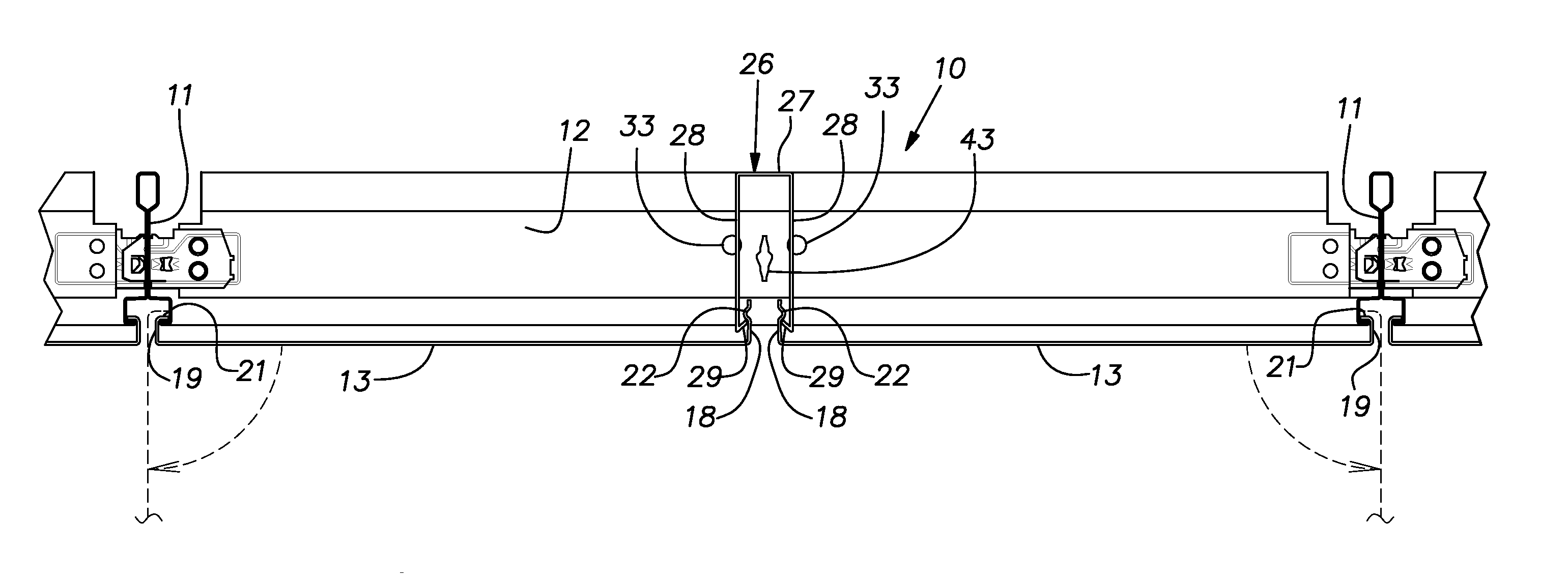
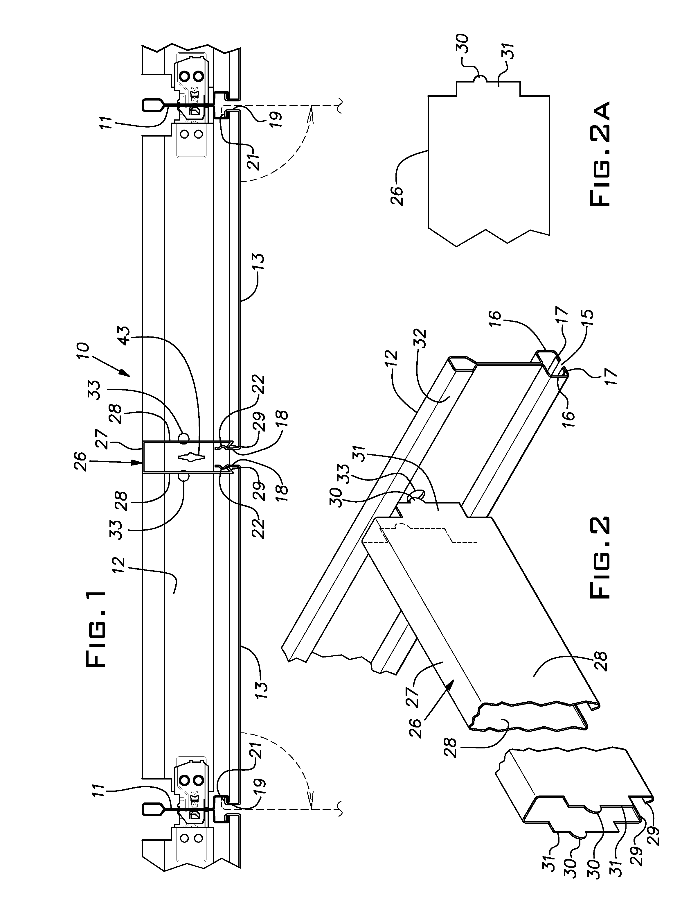
[0019]Referring initially to FIGS. 1, 2 and 2A, there is shown a portion of a suspended ceiling grid system 10. The system 10 includes main runners 11, cross runners 12, and hinge snap-up panels 13. The aforementioned U.S. Pat. Nos. 4,535,580, 4,696,142, and 6,467,228, incorporated herein by reference, disclose various details and aspects of these components. A common manner of constructing a ceiling grid is to use main tees or runners 11, typically 10′ or 12′ long and joined end-to-end. The main tees 11 are suspended, from overhead superstructure by wires for example, so that they are parallel to one another and are spaced on 4′ centers. Dimensions given herein can have metric equivalents depending on the country of origin or use. Nominal 4′ long cross runners 12 are assembled in regularly spaced main runner slots. Typically, the 4′ cross runners will be spaced on 2′ centers. Extending between the 4′ long grid runners 12 are nominally 2′ long cross runners at least some of which ar...


PUM


Abstract

A suspended ceiling comprising a grid formed of intersecting grid runners and snap-up panels supported on the grid runners, the grid runners dividing a ceiling area into standard modules, the pans being formed of sheet material and each having its sides sized to cover the module size while leaving a space at visible faces thereof between adjacent panels when in an installed position on the grid, at least one adjacent pair of panels being displaceable from their installed positions, the gap between a pair of displaceable panels being closed by a removable runner or the displaceable panels so that when the displaceable panels are displaced from their installed position and any removable runner is removed, an access opening of twice the standard module is made available for accessing the area above the ceiling while adjacent panels at longitudinal ends of the gap between the displaceable panels can remain in respective installed positions.

Description

BACKGROUND OF THE INVENTION[0001]The invention relates to suspended ceiling systems and, in particular, to components of such systems that facilitate access to the space above a ceiling.PRIOR ART[0002]U.S. Pat. No. 4,535,580 discloses a screw slot runner for a suspended ceiling grid and U.S. Pat. No. 4,696,142 discloses a snap-up panel useful with the screw slot style grid runner. U.S. Pat. No. 6,467,228 discloses edge configurations for snap-up panels that serve as hinges to enable the panels to be folded downwardly for access to the space or plenum above the ceiling while remaining supported on the grid.[0003]Panels of the type disclosed in these referenced patents are typically made of metal or rigid plastic sheet stock. Besides affording a distinctive look, this type of panel is quite durable thus making it a good choice where access to the plenum is anticipated to be necessary, especially when it is expected to be relatively frequent. Where the grid spacing and panels are nomin...

Claims


Application Information

Patent Timeline
Patent Type & Authority Patents(United States)
IPC IPC(8): E04B9/00
CPCE04B9/003E04B9/0414E04B9/0478E04B9/127
Inventor WENDT, ALAN C.
Owner USG INTERIORS INC
Why Eureka
Try Eureka