Air intake, in particular for an aircraft chaff dispenser

a technology of air intake and chaff dispenser, which is applied in the field of air intake, can solve the problems of affecting the defence capacity of the aircraft, the risk of mechanical faults, and the recirculation of the dispenser, and affecting the ability of the aircraft to be protected

Active Publication Date: 2013-07-16
ALENIA AERONAUTICA SPA
View PDF47 Cites 5 Cited by
  • Summary
  • Abstract
  • Description
  • Claims
  • Application Information

AI Technical Summary

Benefits of technology

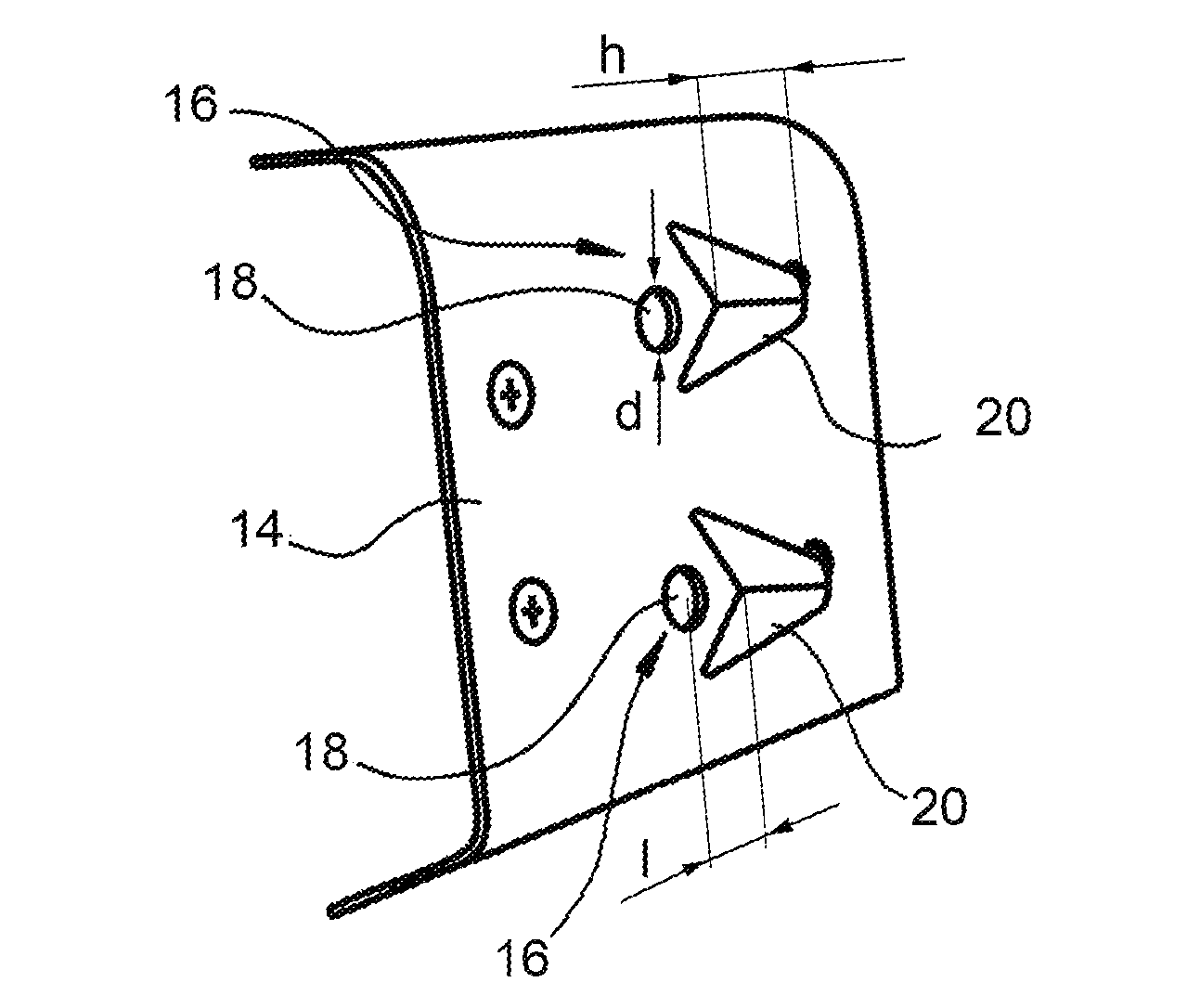
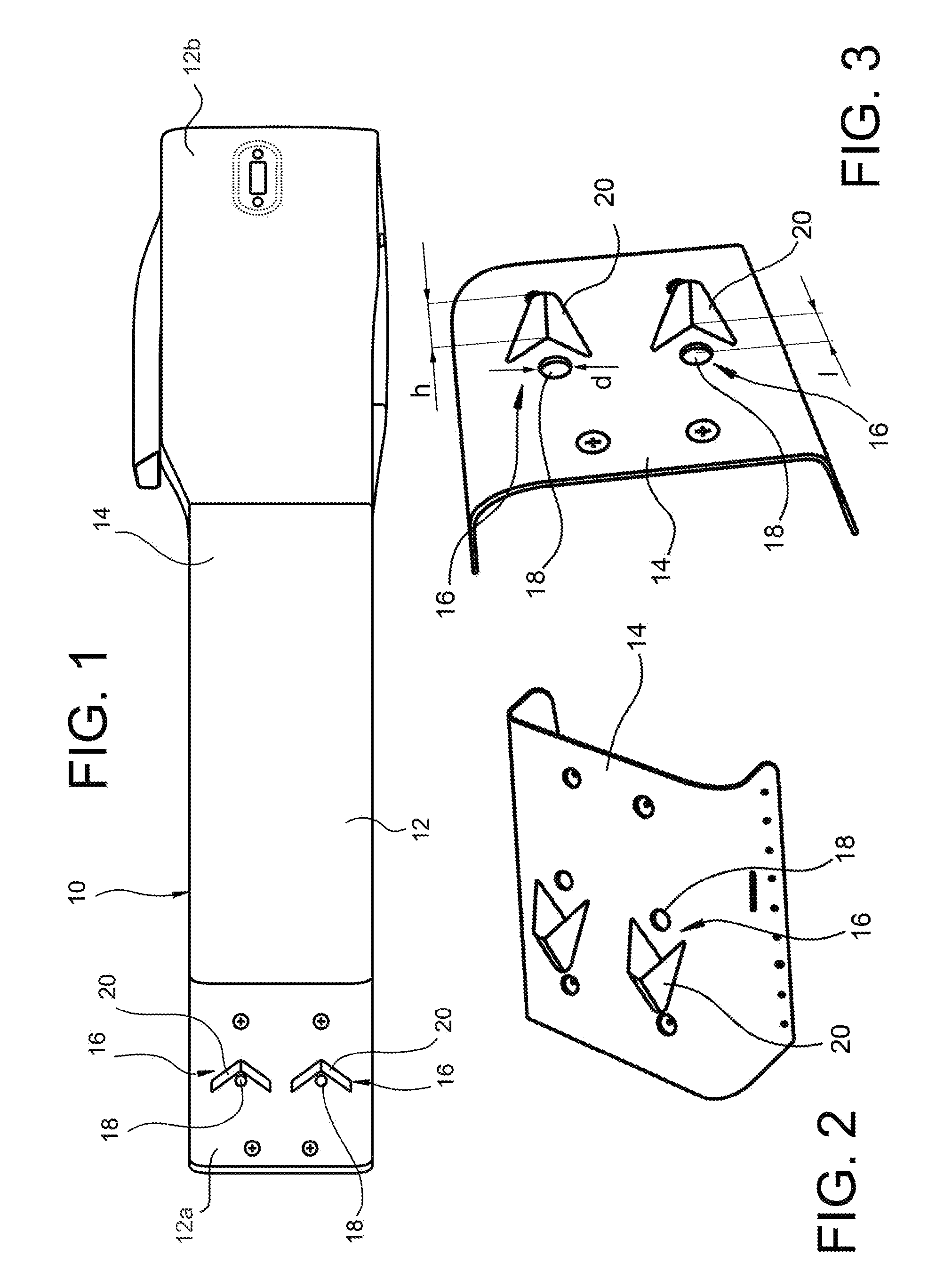
[0010]By virtue of the fact that the air intake comprises a through-hole formed in a wall of a housing and a fence which is suitably shaped and suitably spaced from the hole, the pressure increase effect is maximized in the part of the housing in which the air intake is provided. If such an air intake is mounted on the front of the side walls of the housing of an aircraft chaff dispenser, the risk of the packets of chaff being sucked back into or recirculated inside the dispenser is therefore minimized and at the same time the risk of entry of the gases emitted by the missiles launched by the aircraft and therefore of damage to the packets of chaff contained inside the dispenser is minimized.
[0011]Moreover, owing to the small height of the fences of the lateral air intakes, both the aerodynamic drag and the radar visibility of the dispenser are reduced.

Problems solved by technology

The main problem affecting the known aircraft chaff dispenser consists in that a negative pressure gradient is created between the front part of the housing (in which the driving mechanism is received) and the rear part of the housing (in which the packets of chaff are received and from which they are ejected), which negative pressure gradient causes the chaff ejected from the chaff dispenser to be sucked back into or recirculated inside it, with a consequent risk of faults both of a mechanical nature, such as seizing of the driving mechanism, and of an electronic nature, in particular problems of electromagnetic interference with the electronic control circuits of the dispenser and with the remaining aircraft defence circuitry and sensor equipment mounted on the housing of the dispenser.
The presence of lateral air intakes involves, however, the risk that the gases emitted by the missiles launched by the aircraft enter inside the dispenser and hit the packets of chaff contained inside it, damaging them irremediably and therefore negatively affecting the defence capacity of the aircraft.

Method used


Image

  • Air intake, in particular for an aircraft chaff dispenser
  • Air intake, in particular for an aircraft chaff dispenser

Examples


Embodiment Construction

[0015]With reference initially to FIG. 1, an aircraft chaff dispenser according to the present invention is generally indicated 10 and basically includes:[0016]an elongated hollow housing 12 intended to be fixed to the fuselage or to a wing of the aircraft so as to be oriented in the longitudinal direction of the aircraft, the housing having a closed front end 12a and an open rear end 12b; [0017]a driving mechanism (known per se and not shown) received inside the housing 12 and operable to push backwards (relative to the direction of travel of the aircraft) packets of chaff (known per se and not shown) so as to eject them one at a time from the rear opening 12b; and[0018]an electronic circuit controlling the driving mechanism, and, where applicable, part of the aircraft defence sensor equipment and electronic circuitry (known per se and not shown).

[0019]The housing 12 has preferably a square or rectangular cross-section with a pair of vertical side walls 14 (only one of which is sho...


PUM


Abstract

An aircraft chaff dispenser includes an elongated hollow housing intended to be fixed to the structure of the aircraft so as to be oriented in the longitudinal direction of the aircraft. The housing has a pair of side walls and the front of each side wall is provided with a pair of lateral air intakes each having a circular through-hole with a diameter d and a fence located behind the hole in the longitudinal direction, or in the direction of travel, of the aircraft at a distance 1 from the center of the hole and having a shape in the form of a horizontally lying V with its vertex directed away from the hole. The diameter d of the hole is between 8 and 12 mm. The ratio h / 1 between the height h of the fence at the vertex of the V and the distance 1 is between 0.8 and 1, while the ratio h / d between the height h and the diameter d is between 1.5 and 2.

Description

[0001]This application is a National Stage Application of PCT / IB2009 / 050732, filed 24 Feb. 2009, which claims benefit of Ser. No. TO2008A000142, filed 28 Feb. 2008 in Italy and which applications are incorporated herein by reference. To the extent appropriate, a claim of priority is made to each of the above disclosed applications.FIELD OF THE INVENTION[0002]The present invention relates generally to an air intake and more particularly to an air intake for an aircraft chaff dispenser.BACKGROUND OF THE INVENTION[0003]Typically an aircraft chaff dispenser includes:[0004]an elongated hollow housing intended to be fixed to the fuselage or to a wing so as to be oriented in the longitudinal direction of the aircraft, the housing having a closed front end and an open rear end;[0005]a driving mechanism received inside the housing and operable to push backwards (relative to the direction of forward movement of the aircraft) packets of chaff and eject them one at a time from the rear opening;...

Claims


Application Information

Patent Timeline
Patent Type & Authority Patents(United States)
IPC IPC(8): B64D1/00B64D33/02
CPCF41H11/02F42B12/70F42B12/48F42B5/15
Inventor GEMMA, RICCARDO
Owner ALENIA AERONAUTICA SPA
Why Eureka
Try Eureka