
Flux focusing magnetic gear assembly using ferrite magnets or the like

Active Publication Date: 2017-01-05
JUNIVERSITI OF NORT KAROLINA EHT SHARLOTT
View PDF0 Cites 6 Cited by
  • Summary
  • Abstract
  • Description
  • Claims
  • Application Information

AI Technical Summary

Benefits of technology

The present invention provides a flux focusing magnetic gear assembly that uses a special design to maximize the performance of the gear assembly. The gear assembly includes an inner rotor, middle rotor, and outer stator, each with a unique design to achieve optimal magnetic field distribution. The inner rotor has concentrically disposed inner magnets and interstitial members, while the middle rotor has concentrically disposed poles and interstitial members. The outer stator has concentrically disposed windings. The design of the inner and middle rotors allows for efficient energy transfer and minimizes magnetic field leakage. The performance of the gear assembly is maximized by optimizing the length and width of the magnets and interstitial members.

Problems solved by technology

This can become prohibitively expense, and the use of a less expensive ferrite material is certainly preferred, although the inferior performance of the ferrite material must be compensated for via a superior magnetic gear assembly design.
Generally, given such low speeds, extremely large or extremely high force density devices are required to generate significant power.

Method used


Image

  • Flux focusing magnetic gear assembly using ferrite magnets or the like
  • Flux focusing magnetic gear assembly using ferrite magnets or the like
  • Flux focusing magnetic gear assembly using ferrite magnets or the like

Examples


Embodiment Construction

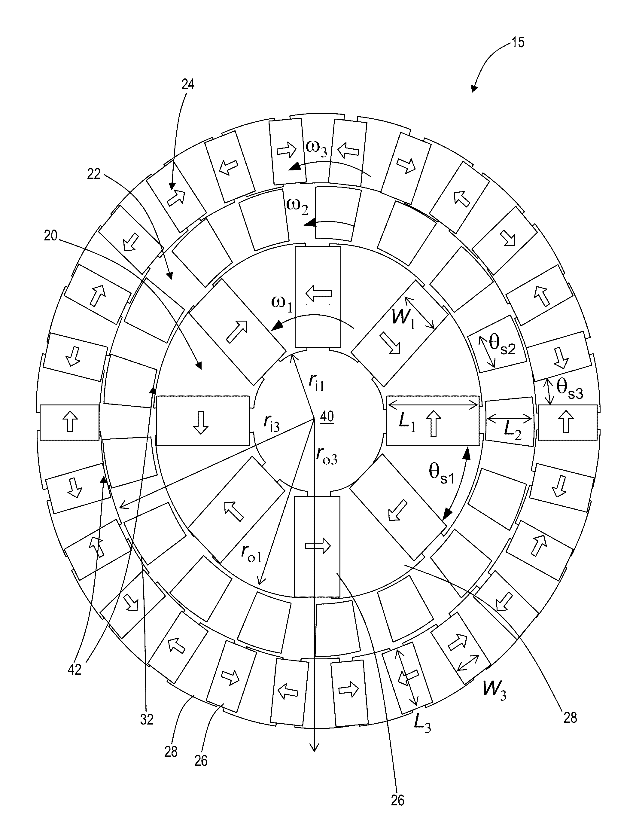
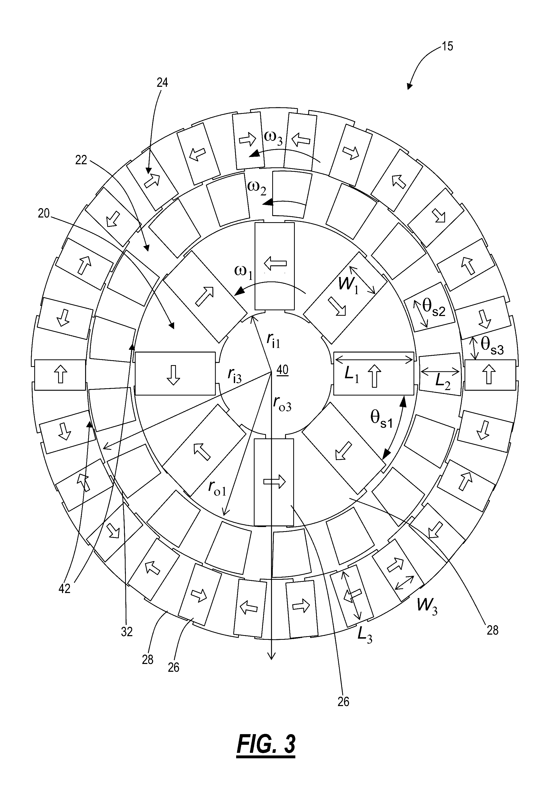
[0021]Referring specifically to FIG. 3, in one exemplary embodiment, the flux focusing magnetic gear assembly 15 of the present invention includes an inner rotor 20 including P1 magnet pole pairs that rotates at angular velocity ω1, a middle rotor 22 including n2 ferromagnetic steel poles or the like that rotates at angular velocity ω2, and an outer rotor 24 including P3 magnet pole pairs that rotates at angular velocity ω3. The magnetization directions of the magnets 26 are aligned as illustrated, in a flux focusing arrangement, also referred to herein as a spoke type arrangement. Specifically, the magnets 26 are purposefully magnetized in a substantially azimuthal direction, contrary to the radial direction that has been used conventionally.

[0022]Related to the inner rotor 20, the plurality of magnets 26 are separated by a plurality of rectangular, wedge shaped, or annular steel teeth 28 or the like for enhancing flux focusing functionality. The performance of the magnetic gear as...


PUM


Abstract

The present invention relates generally to a flux focusing magnetic gear assembly using ferrite magnets or the like. The present invention also relates generally to a flux focusing magnetic gear assembly using ferrite magnets or the like that incorporates an outer stator assembly that converts a variable input to a constant output. The present invention further relates generally to an axially aligned flux focusing magnetic gear assembly using ferrite magnets or the like. The improved flux focusing magnetic gear assemblies of the present invention find applicability in traction, wind, and ocean power generation, among other applications.

Description

CROSS-REFERENCE TO RELATED APPLICATIONS[0001]The present patent application / patent is a divisional of co-pending U.S. patent application Ser. No. 14 / 240,049, filed on Feb. 21, 2014, and entitled “FLUX FOCUSING MAGNETIC GEAR ASSEMBLY USING FERRITE MAGNETS OR THE LIKE,” the contents of which are incorporated in full by reference herein.FIELD OF THE INVENTION[0002]The present invention relates generally to an improved flux focusing magnetic gear assembly using ferrite magnets or the like. The present invention also relates generally to an improved flux focusing magnetic gear assembly using ferrite magnets or the like that incorporates an outer stator assembly that converts a variable input to a constant output. The present invention further relates generally to an improved axially aligned flux focusing magnetic gear assembly using ferrite magnets or the like. The improved flux focusing magnetic gear assemblies of the present invention find applicability in traction, wind, and ocean pow...

Claims


Application Information

Patent Timeline
IPC IPC(8): H02K49/10
CPCH02K49/102
Inventor BIRD, JONATHAN
Owner JUNIVERSITI OF NORT KAROLINA EHT SHARLOTT
Learn More