
Battery storage system

a battery storage and battery technology, applied in the field of battery storage systems, can solve the problems of not being able to utilize the remainder, and achieve the effect of reducing the total power

Inactive Publication Date: 2013-07-16
HITACHI LTD +1
View PDF8 Cites 14 Cited by
  • Summary
  • Abstract
  • Description
  • Claims
  • Application Information

AI Technical Summary

Benefits of technology

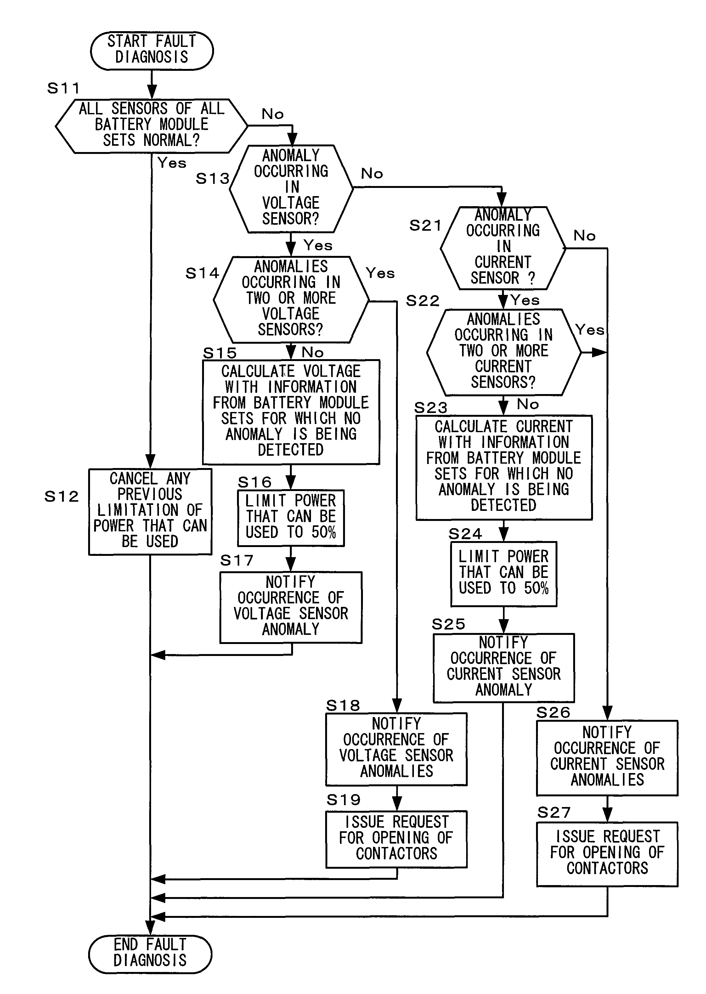
The patent describes a battery storage system that has a control device that can reduce the overall power of the system based on sensor faults. This can help to prevent overloading the system and ensure that all components are operating correctly. The control device can reduce power based on the number of sensors that are faulty or the type of sensor that is faulty. This can improve the overall efficiency and reliability of the battery storage system.

Problems solved by technology

However, with a battery storage system in which a plurality of battery modules are electrically connected in series-parallel and that can supply high power, as in Japanese Laid-Open Patent Publication 2007-151396, if a fault has been detected in one of the battery modules, then, in the prior art, control has been performed so as to stop input and output to and from the battery storage system even if the rest of the battery modules are operating normally, and accordingly it has not been possible to utilize the remainder of the battery modules, that are still in good order.

Method used


Image

  • Battery storage system
  • Battery storage system
  • Battery storage system

Examples


Embodiment Construction

[0022]In the following, an embodiment of the present invention will be explained.

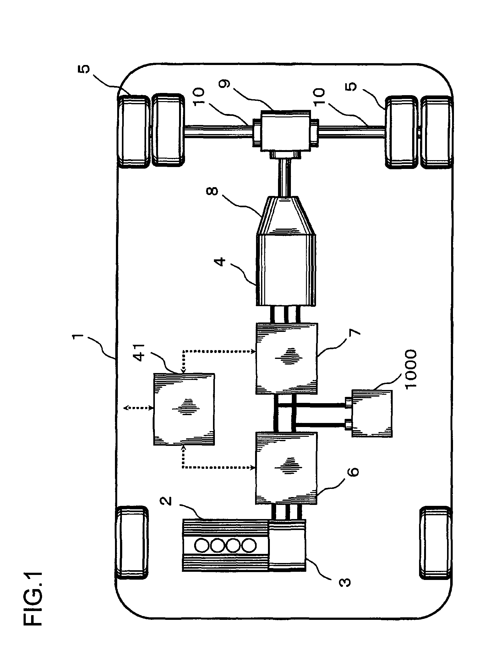
[0023]In the embodiments explained below, the present invention is explained by giving an example of use thereof as a drive power supply for a drive system for a large sized hybrid vehicle.

[0024]Such a large sized hybrid vehicle may be a public vehicle such as a hybrid bus or the like, or a cargo vehicle such as a hybrid truck or the like. The embodiment below will be described in terms of a hybrid bus.

[0025]Moreover, the structure of the embodiment described below may also be applied to a railroad vehicle or the like, such as a hybrid train or the like.

[0026]This embodiment will now be explained in concrete terms with reference to the drawings.

[0027]First, the general layout of a drive system for a large sized electric hybrid vehicle will be explained with reference to FIG. 1.

[0028]The drive system of the hybrid vehicle 1 of this embodiment is constructed according to the so called series hybrid princi...


PUM

PropertyMeasurementUnit
rated voltageaaaaaaaaaa
drive voltageaaaaaaaaaa
supplied voltageaaaaaaaaaa

Abstract

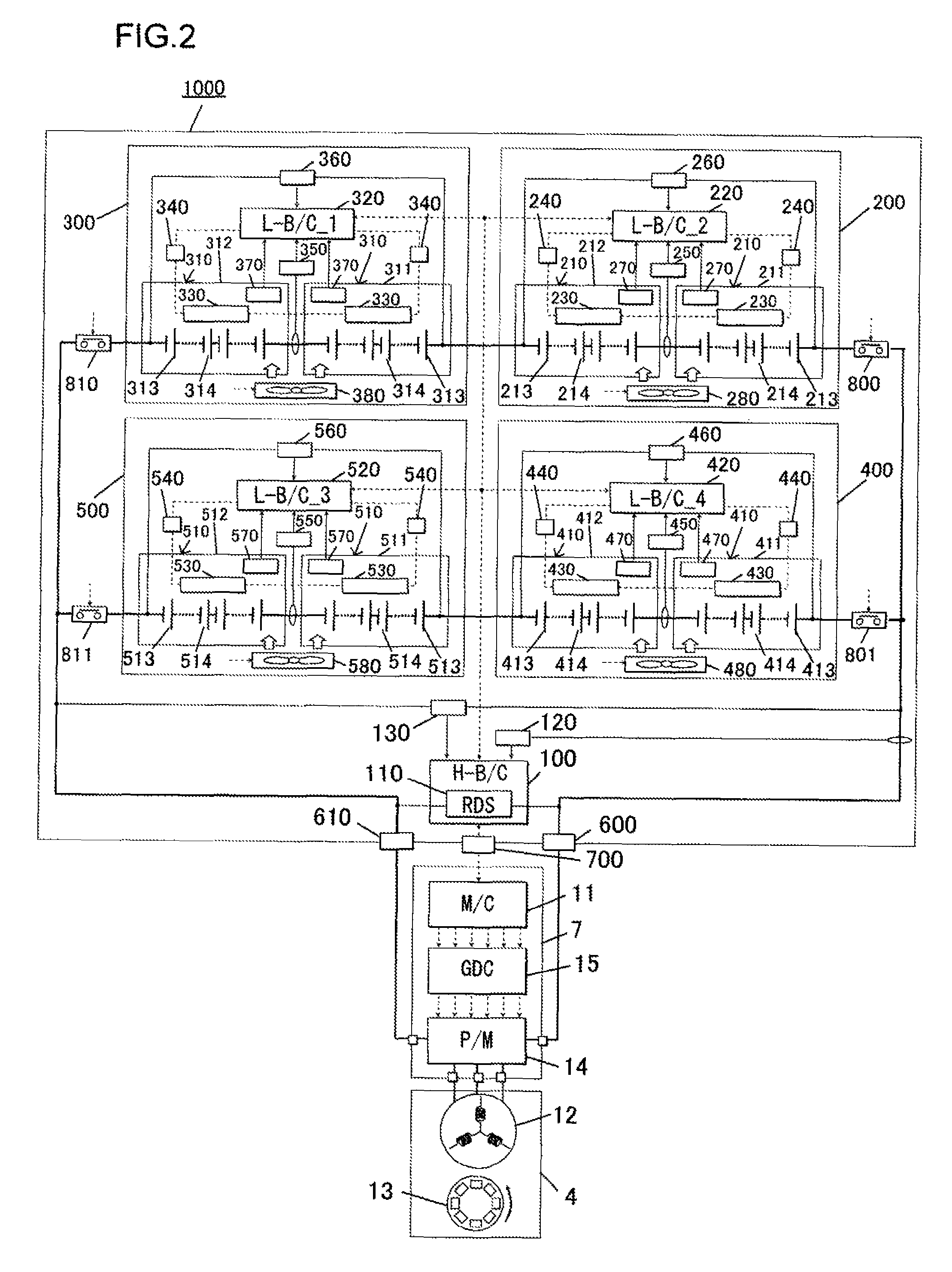
A battery storage system includes: a plurality of battery modules that are electrically connected in series and in parallel, each comprising a plurality of battery cells; a plurality of sensors provided to each of the plurality of battery modules, that output at least signals corresponding to voltage and current of the each of the battery modules; a plurality of first control devices each of which is provided to the each of the plurality of battery modules, and obtains a power that can be inputted and outputted to and from the each of the battery modules based upon the voltage and current obtained from the output signals of the sensors of the each of the battery modules; and a second control device that performs overall control of the plurality of first control devices, and if a fault of a sensor in any one of the plurality of battery modules has occurred, the second control device obtains a total power that can be inputted and outputted to and from the all of the battery modules, based upon powers each of which can be inputted and outputted to and from each of other battery modules than a battery module in which the sensor has detected the fault, and outputs information of the total power.

Description

INCORPORATION BY REFERENCE[0001]The disclosure of the following priority application is herein incorporated by reference: Japanese Patent Application No. 2008-304285, filed Nov. 28, 2008.BACKGROUND OF THE INVENTION[0002]1. Field of the Invention[0003]The present invention relates to a technique related to a battery storage system, and, as a representative, relates to a technique for impeding deterioration of the function of the device as a power supply.[0004]2. Description of Related Art[0005]As a battery storage system in which a plurality of battery modules are electrically connected in series-parallel and that can supply high power, there is known, for example, the one disclosed in Japanese Laid-Open Patent Publication 2007-151396. In this Japanese Laid-Open Patent Publication 2007-151396, there is disclosed a technique of monitoring the operating conditions of the battery modules by detecting voltage, current, and temperature for each battery module with sensors of various types...

Claims


Application Information

Patent Timeline
Patent Type & Authority Patents(United States)
IPC IPC(8): H01M2/00H01M10/48B60L3/00H02J7/00H02J7/02
CPCH01M10/482H01M10/441G01R35/00H01M10/0525Y02T10/7011Y02E60/10
Inventor UEDA, MASAHIROAOSHIMA, YOSHINORI
Owner HITACHI LTD
Learn More