Vertical axis wind turbine and generator therefore

a generator and vertical axis technology, applied in the direction of magnetic circuit rotating parts, magnetic circuit shape/form/construction, greenhouse gas reduction, etc., can solve the problems of parasitic power consumption by constant, low efficiency of current horizontal axis wind turbines, and drawbacks

Inactive Publication Date: 2013-07-16
GRASSMAN DEREK
View PDF23 Cites 23 Cited by
  • Summary
  • Abstract
  • Description
  • Claims
  • Application Information

AI Technical Summary

Benefits of technology

[0023]In another aspect of the invention, a sail assembly is coupled to the rotor assembly. The first operative voltage output stage is added to the voltage device when the wind speed reaches 5 miles per hour.

Problems solved by technology

Horizontal axis wind turbines have traditionally been utilized to harness wind energy, but they suffer from drawbacks.
For example, current horizontal axis wind turbines have low efficiency due to large gears and transmissions.
Parasitic power is consumed by the constant reorientation of the blades into the wind stream.
Horizontal axis wind turbines are unable to harness turbulent winds, and are susceptible to damage in high winds.
However, several common problems have stymied efforts to bring vertical axis wind turbines into broad commercial acceptance.
One noted problem with vertical axis wind turbines is that they suffer inefficiencies due to drag during part of the rotation, which is a consequence of the vane shapes and gearing.
One noted drawback to that design was that the flat fans were not very aerodynamic in design, and thus operation was rough and slow, with the fans being pulled out of position by centrifugal force.
The wind turbine exhibited drag rotation over 180 degrees of each revolution, but vane interference of the upwind vane over the downwind vane in its wind shadow reduced overall effectiveness.
One drawback to this approach was that the positioning of the airfoils was only effective in the directly windward and directly leeward positions, using crosswind lift force in both cases.
A drawback to this design, however, was that the efficiency was limited because the airfoils rotated through only about a 90 degree arc (out of a possible 360 degrees) and were constrained by stops.
A further drawback to the various vertical axis wind turbines is similar to those inefficiencies found in the horizontal models, namely that there is a relatively large amount of weight carried by the bearings that support vertically rotating components.
In addition to the loss of energy resulting from the friction between the relative components, this leads to the need to replace bearings on a regular basis.

Method used


Image

  • Vertical axis wind turbine and generator therefore
  • Vertical axis wind turbine and generator therefore
  • Vertical axis wind turbine and generator therefore

Examples


Embodiment Construction

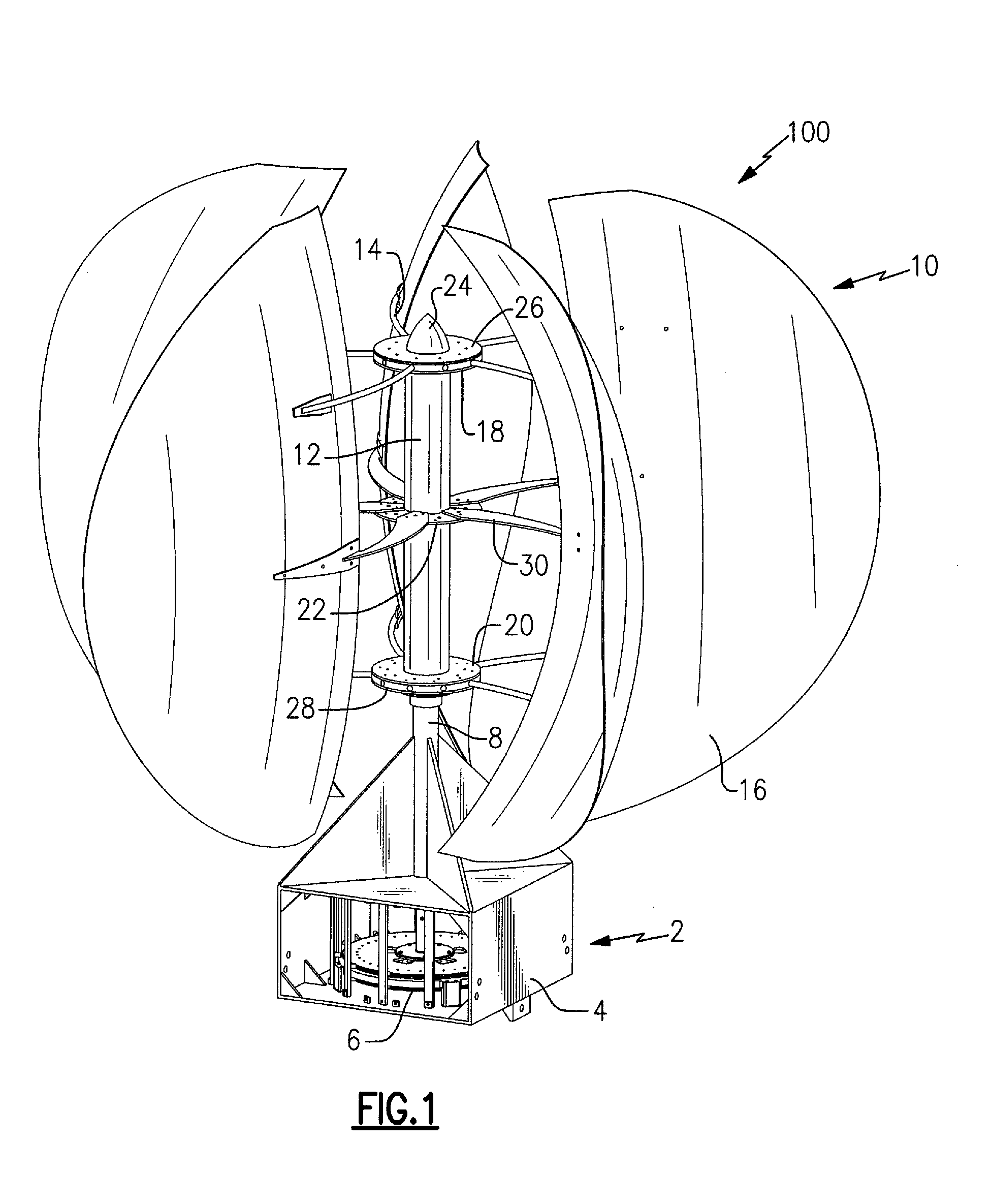
[0032]Referring to FIG. 1, a vertical axis wind turbine 100 generally includes a support base 2 that, in one example, mounts to the roof of a house. In the disclosed embodiment, the support base 2 includes a housing portion 4 in which a multistage axial flux generator 6 is located. The support base 2 may further include a vertically-extending support column 8 to provide support for a sail assembly 10 mounted thereon.

[0033]The sail assembly 10 includes a sail hub 12, a plurality of sail mount arms 14 fixed to the sail hub 12, and a plurality of sails 16 attached to the sail mount arms 14. The sail hub 12 is a hollow cylinder with an upper flange 18, a lower flange 20, and a central stiffening ring 22. A cap 24 protects the rotating components from exposure to the elements. The sail mount arms 14 at the top of the sail hub 12 are secured in between the upper flange 18 and a upper hub 26. The sail mount arms 14 at the bottom of the sail hub 12 are secured in between the lower flange 20...


PUM


Abstract

A vertical wind turbine is provided that includes a support base defined about an axis, a bearing assembly, a drive shaft having a proximal end and an opposing distal end, and a multistage axial flux generator. The bearing assembly includes a fixed ring and a rotating ring, wherein the fixed ring is coupled to the support base. The drive shaft is coupled to the rotating ring of the bearing assembly, and a plurality of sails are coupled to the drive shaft. The multistage axial flux generator includes a rotor assembly coupled to the drive shaft and a stator assembly coupled to the support base. The rotor assembly includes a plurality of permanent magnets, and the stator assembly includes a plurality of coils defining at least two voltage output stages. The permanent magnets on the rotor assembly are close-coupled to the coils on the stator assembly.

Description

CROSS REFERENCE TO RELATED APPLICATION[0001]Reference is made to and this application claims priority from and the benefit of U.S. Provisional Application Ser. No. 61 / 213,281, filed May 22, 2009, entitled “VERTICAL AXIS WIND TURBINE”, which application is incorporated herein in its entirety by reference.FIELD OF THE INVENTION[0002]This disclosure relates generally to vertical axis wind turbines and, more specifically, to a vertical axis wind turbine having a multistage axial flux generator.BACKGROUND OF THE INVENTION[0003]There is a growing need for clean energy in the world, and one of the cleanest and most abundant sources is wind energy. Horizontal axis wind turbines have traditionally been utilized to harness wind energy, but they suffer from drawbacks. For example, current horizontal axis wind turbines have low efficiency due to large gears and transmissions. Parasitic power is consumed by the constant reorientation of the blades into the wind stream. Horizontal axis wind turbi...

Claims


Application Information

Patent Timeline
Patent Type & Authority Patents(United States)
IPC IPC(8): F03D9/00
CPCF03D3/005F03D3/062F03D9/002F03D11/0008H02K7/183H02K21/24F05B2220/7066F05B2220/7068F05B2240/212F05B2240/30Y02E10/74F03D80/70F03D9/25Y02E10/728F03D13/20F03D3/06H02K7/18
Inventor GRASSMAN, DEREK
Owner GRASSMAN DEREK
Why Eureka
Try Eureka