Stroller and brake mechanism thereof

a technology of brake mechanism and stroller, which is applied in the direction of braking system, transportation and packaging, animal drawn vehicles, etc., can solve the problems of increased labor, increased stress on the user, and fragile springs, and achieves simple structure, high reliability, and convenient operation.

Active Publication Date: 2013-07-23
WONDERLAND SWITZERLAND AG
View PDF9 Cites 14 Cited by
  • Summary
  • Abstract
  • Description
  • Claims
  • Application Information

AI Technical Summary

Benefits of technology

[0008]An objective of the invention is to provide a brake mechanism for a stroller with simple structure, convenient operation, and high reliability.
[0009]To achieve the aforesaid objective, a brake mechanism of the invention for a stroller comprises an axle, a wheel and at least one brake fixing seat disposed at an inner side of the wheel. The brake fixing seat comprises a brake assembly and a fixing seat. The brake assembly comprises a pedal assembly and a brake member. The brake member has at least one abutting portion and at least one brake arm. The brake assembly further comprises a pushing member for urging the abutting portion. A brake hub is disposed at the inner side of the wheel. A plurality of recesses is formed on the brake hub and is arranged compactly. The axle passes through the pedal assembly, the brake member and the fixing seat sequentially. The pedal assembly is used to drive the pushing member to push the abutting portion, such that the brake member moves toward the brake hub until the brake arm extends into the recesses, so as to brake the stroller. The brake mechanism has advantages of simple structure, convenient operation, and high reliability.

Problems solved by technology

However, to overcome the elastic force of the spring, a user usually has to operate the operating member with an extra force when braking the stroller.
It is strenuous for the user.
Furthermore, the spring will become fragile after multiple operations and then the deformed spring will lose function and has to be replaced accordingly.
In other words, the conventional brake mechanism has relative short service life and low reliability.

Method used


Image

  • Stroller and brake mechanism thereof
  • Stroller and brake mechanism thereof
  • Stroller and brake mechanism thereof

Examples


first embodiment

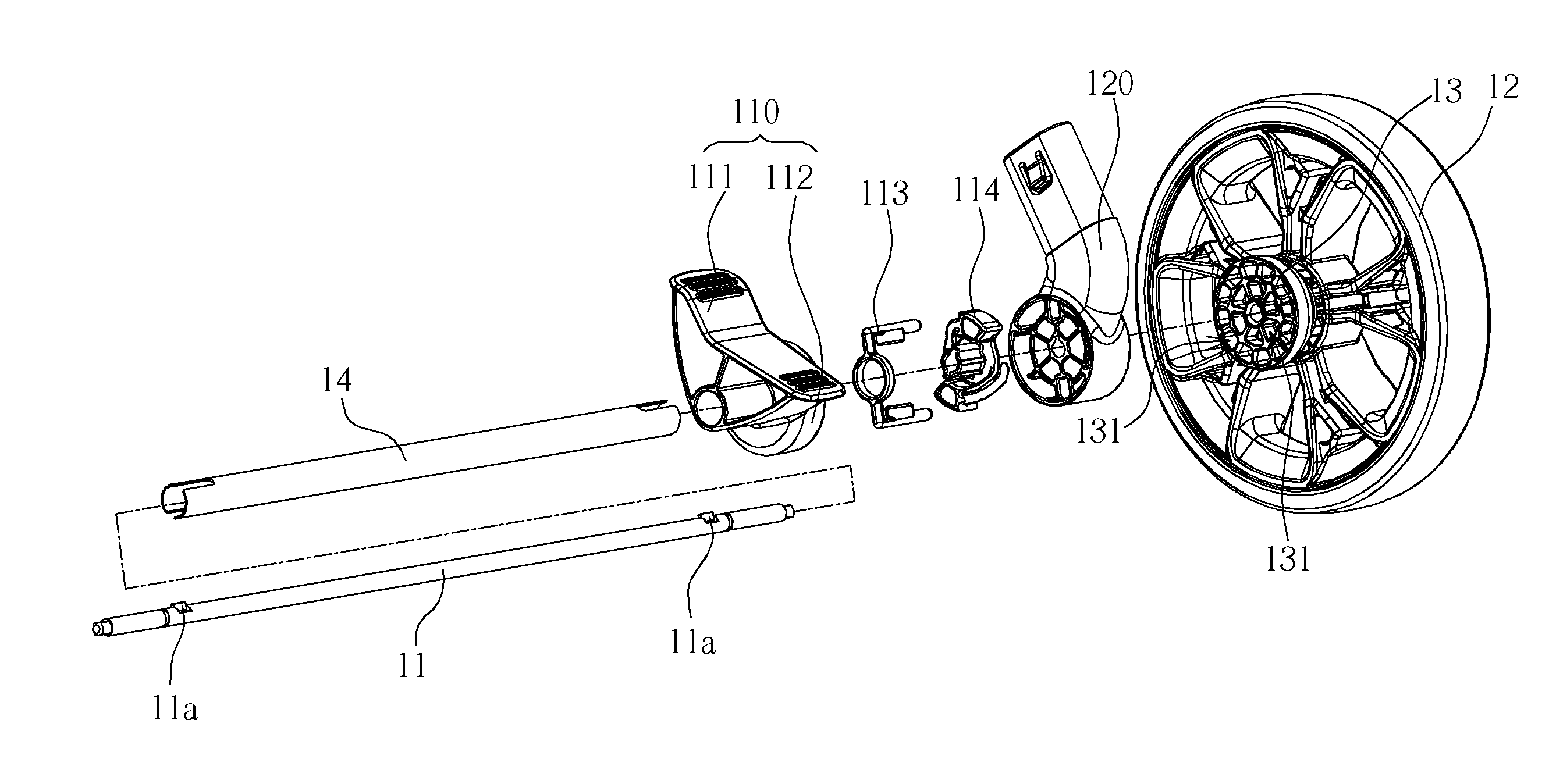
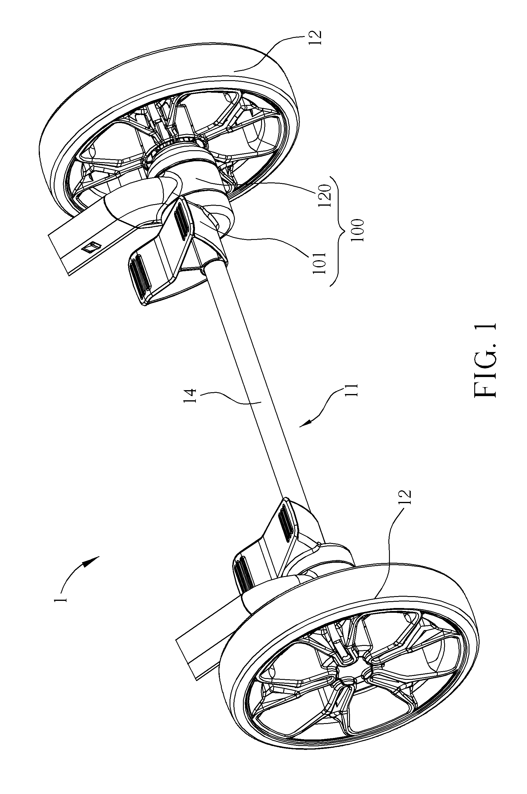
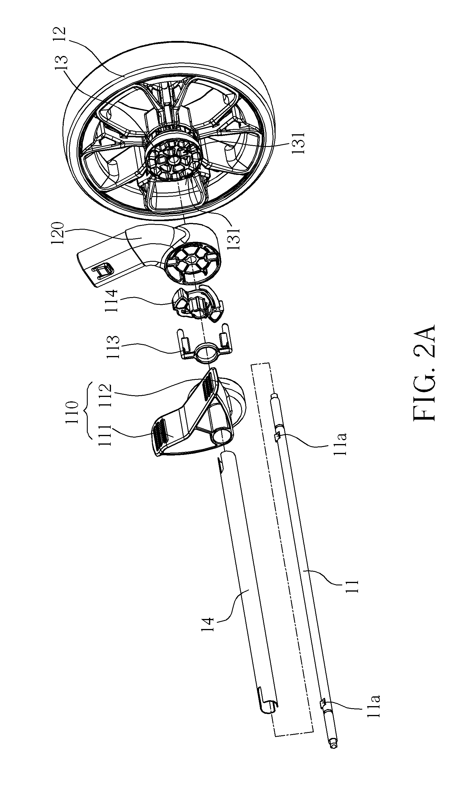
[0044]Referring to FIGS. 1 to 2B, the brake mechanism 1 of the invention for a stroller comprises an axle 11, two wheels 12, a linking tube 14 and at least one brake fixing seat 100, wherein the axle 11 is disposed in the linking tube 14 and the brake fixing seat 100 is disposed at an inner side of the wheel 12 and on the axle 11. In this invention, two brake fixing seats 100 are disposed at the inner side of the two wheels 12 respectively. Since the structures of the two brake fixing seats 100 are the same with each other, only one of the brake fixing seats 100 is described in the following.

[0045]As shown in FIGS. 1 to 3, the brake fixing seat 100 comprises a brake assembly 101 and a fixing seat 120 connected to the brake assembly 101. After assembling the brake fixing seat 100, the fixing seat 120 is located between the brake assembly 101 and the wheel 12. A brake hub 13 is disposed at the inner side of the wheel 12. A plurality of recesses 131 is formed on the brake hub 13 and i...

second embodiment

[0056]FIGS. 9 to 14 illustrate a brake mechanism 1′ according to the invention.

[0057]Referring to FIGS. 9, 10 and 16, as mentioned in the first embodiment, the brake mechanism 1′ (shown in FIG. 16) of this embodiment comprises an axle 11, two wheels 12 and at least one brake fixing seat 100′, wherein the brake fixing seat 100′ is disposed at an inner side of the wheel 12 and on the axle 11. The brake fixing seat 100′ comprises a brake assembly 101′ and a fixing seat 120′ connected to the brake assembly 101′. The main difference between the brake assembly 101′ of this embodiment and the brake assembly 101 of the first embodiment is that the brake assembly 101′ comprises a pedal assembly 110′, a brake member 113′ movably connected to the pedal assembly 110′, and a spring 114′ for releasing the brake function. The pedal assembly 110′ comprises a pedal 111 and a first hub 112′ connected to the pedal 111. The main difference between this embodiment and the first embodiment is the interac...


PUM


Abstract

A brake mechanism for a stroller includes an axle, a wheel and at least one brake fixing seat disposed at an inner side of the wheel. The brake fixing seat includes a brake assembly and a fixing seat. The brake assembly includes a pedal assembly and a brake member. The brake member has at least one abutting portion and at least one brake arm. The brake assembly includes a pushing member for pushing the abutting portion. A brake hub is disposed at the inner side of the wheel. A plurality of recesses is formed on the brake hub and arranged compactly. The axle passes through the pedal assembly, the brake member, and the fixing seat. The pedal assembly is used to drive the pushing member to push the abutting portion and the brake member moves toward the brake hub until the brake arm extends into the recesses.

Description

BACKGROUND OF THE INVENTION[0001]1. Field of the Invention[0002]The invention relates to a brake mechanism and, more particularly, to a brake mechanism for a stroller and a stroller equipped with the brake mechanism.[0003]2. Description of the Prior Art[0004]To ensure driving security, most of conventional strollers are equipped with brake mechanism. For a conventional brake mechanism, a brake member, which is fixed on a wheel seat, is inserted into a hole / recess, which is formed on a brake hub of a wheel, so as to achieve brake function.[0005]A conventional brake mechanism comprises a wheel below a frame, a fixing member disposed on the wheel, and a rod member disposed on the frame. A brake hole / recess is formed on the fixing member and a brake member is pivotally disposed on the rod member. The brake member can be operated between a brake position and a release position. When the brake member is situated at the brake position, the brake member is located in the brake hole / recess. ...

Claims


Application Information

Patent Timeline
Patent Type & Authority Patents(United States)
IPC IPC(8): B62B9/08
CPCB62B9/082B62B9/087B62B5/0461B62B5/0433B62B9/08
Inventor CHEN, RUIBINCUI, ZONG-WANG
Owner WONDERLAND SWITZERLAND AG
Why Eureka
Try Eureka