
Intrauterine pressure catheter interface cable system

a technology of pressure catheter and interface cable, which is applied in the direction of cables, insulated conductors, catheters, etc., can solve the problems of inconvenient operation, pressure catheters that do not provide for zeroing operation, and pressure catheters that do not provide for such a zeroing operation suffer

Active Publication Date: 2013-07-23
KPR U S LLC
View PDF36 Cites 15 Cited by
  • Summary
  • Abstract
  • Description
  • Claims
  • Application Information

AI Technical Summary

Benefits of technology

The present invention provides an interface cable system for connecting an intrauterine pressure catheter system and a monitoring system. The system includes a switching element that allows for a zeroing operation of the pressure catheter system, and an indicator to confirm that the switching element has been operated. The system also includes a test plug for verifying the proper functioning of the interface cable system. The technical effects include improved reliability and stability in the connection between the pressure catheter system and the monitoring system, and reduced risk of malfunctions during labor and delivery.

Problems solved by technology

Many conventional pressure catheters do not allow for a zeroing operation to be performed in situ.
Further, the pressure catheters that do provide for such a zeroing operation suffer from a number of deficiencies.
Such an operation is inconvenient because the user holds the button on the interface cable with a first hand and operates the zeroing mechanism on the fetal monitor with the other hand.
Further, the user has no efficient way of knowing if the system is ready for the zeroing process to be performed.
By their nature, such conventional procedures undesirably have a number of sources of potential error (e.g., errors in following a complex multi-step procedure, human error in determining if the screen indicates that the cable is functioning properly, etc.).

Method used


Image

  • Intrauterine pressure catheter interface cable system
  • Intrauterine pressure catheter interface cable system
  • Intrauterine pressure catheter interface cable system

Examples


Embodiment Construction

[0015]As used herein, the terms “zero,”“re-zero,”“zeroing,” and / or “re-zeroing,” even when used with respect to a catheter system itself (e.g., an intrauterine pressure catheter system), refer to the zeroing or re-zeroing operation of the catheter itself, the associated monitoring system, or a combination thereof. Further, with respect to the claims appended hereto, the terms “zero” and / or “zeroing” are intended to encompass zeroing and re-zeroing operations.

[0016]When measuring intrauterine pressure, the pressure is often measured as an offset with respect to a baseline. This baseline is established by zeroing / re-zeroing the catheter system. Thus, in certain systems, each time a new catheter system is coupled to the interface cable a zeroing / re-zeroing operation is performed.

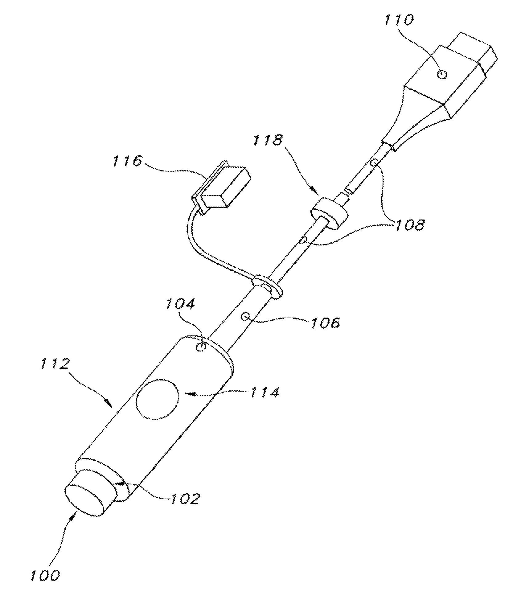
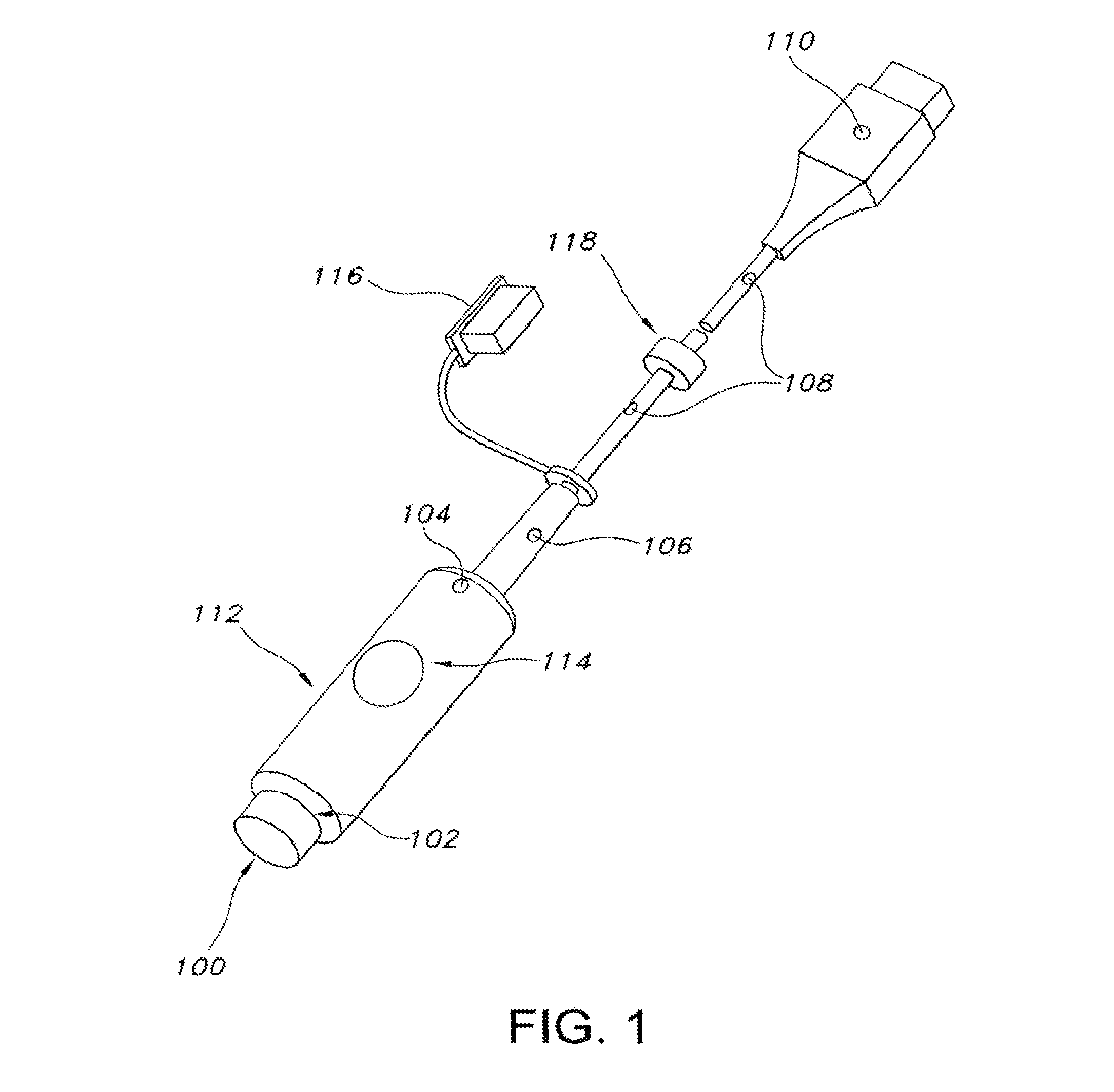
[0017]FIG. 1 is a perspective view of interface cable system 100. Interface cable system 100 is configured to provide electrical interconnection between an intrauterine pressure catheter system and a monitoring...


PUM


Abstract

An interface cable system for providing electrical interconnection between an intrauterine pressure catheter system and a monitoring system is provided. The interface cable system includes a first connector configured to provide electrical interconnection between the interface cable system and the intrauterine pressure catheter system and a second connector configured to provide electrical interconnection between the interface cable system and the monitoring system. The interface cable system also includes a plurality of conductors extending between said first connector and said second connector and a switching element for configuring the interface cable system to provide, upon operation of the switching element, a time period in which a zeroing operation of the intrauterine pressure catheter system may be performed. The interface cable system also includes an indicator for indicating that the switching element has been operated, thereby indicating that the zeroing operation may be performed during the time period.

Description

FIELD OF THE INVENTION[0001]The present invention relates to intrauterine catheters, and more particularly, to a cable system for transmitting signals from an intrauterine pressure catheter.BACKGROUND OF THE INVENTION[0002]In monitoring and / or analyzing fetal contractions, externally applied devices (e.g., tocodynamometers) and intrauterine devices have been used. Regarding intrauterine pressure monitoring, catheters are typically inserted directly into the uterus (e.g., after the amniotic membranes have been broken). Once a catheter has been inserted in the uterus, a pressure measurement is taken by the catheter. The measured pressure is then transferred from the catheter (either electrically or mechanically depending on the type of catheter) to an interface cable. The interface cable then electrically transfers the pressure in the form of an electrical signal to one or more fetal monitors. A number of pressure catheter components and systems are described in U.S. Pat. No. 5,566,68...

Claims


Application Information

Patent Timeline
Patent Type & Authority Patents(United States)
IPC IPC(8): A61B5/103A61B5/117
CPCA61B5/035H01B7/326G01R31/28A61B5/6852A61B2560/045A61B2562/222A61B5/00A61B5/103
Inventor ZAIKEN, ELIOT J.TOOMEY, MARYJO A.LOW, STEWART W.
Owner KPR U S LLC
Learn More