Head mounted display device and image display device

a display device and display device technology, applied in the field of small head mounted display devices, can solve the problems of difficult to properly position difficulty in etc., and achieve the effect of facilitating the exact positioning of the image display section, facilitating the exact positioning of the image display device, and viewing images more easily

Inactive Publication Date: 2013-07-23
SCALAR CORP
View PDF7 Cites 20 Cited by
  • Summary
  • Abstract
  • Description
  • Claims
  • Application Information

AI Technical Summary

Benefits of technology

[0017]The image display section in the head mounted display device according to the present invention may be intended to be moved manually. Alternatively, it may be intended to be moved automatically. In addition, the head mounted display device of the present invention may be the one wherein the image display section is moved manually in one direction and automatically in the other direction, between the standby position and the service position. Automatic movement of the image display section would be convenient for users.
[0035]The glasses to which the image display device is to be attached may be either commercially available normal glasses or purpose-built special glasses. Purpose-built special glasses can facilitate exact positioning of the image display device with respect to the glasses by means of appropriately processing the temples of the glasses to which the image display device is to be attached. Accordingly, it is more convenient in order to provide more exact positioning of the image display section of the image display device.

Problems solved by technology

It is not so easy to properly position the image display device and attach it to the glasses.
The difficulty in exact positioning of the image display device for the attachment to the glasses could be a cause of users' steering clear of using the image display device.

Method used


Image

  • Head mounted display device and image display device
  • Head mounted display device and image display device
  • Head mounted display device and image display device

Examples


Embodiment Construction

[0039]A preferred embodiment of the present invention is described in detail below with reference to the drawings.

[0040]Description in this embodiment will be made about an image display device according to the present invention which forms, when being attached to glasses, a head mounted display device in the present invention together with the glasses. A pair of glasses to which the image display device is attached is an example of the head mounted display device of the present invention.

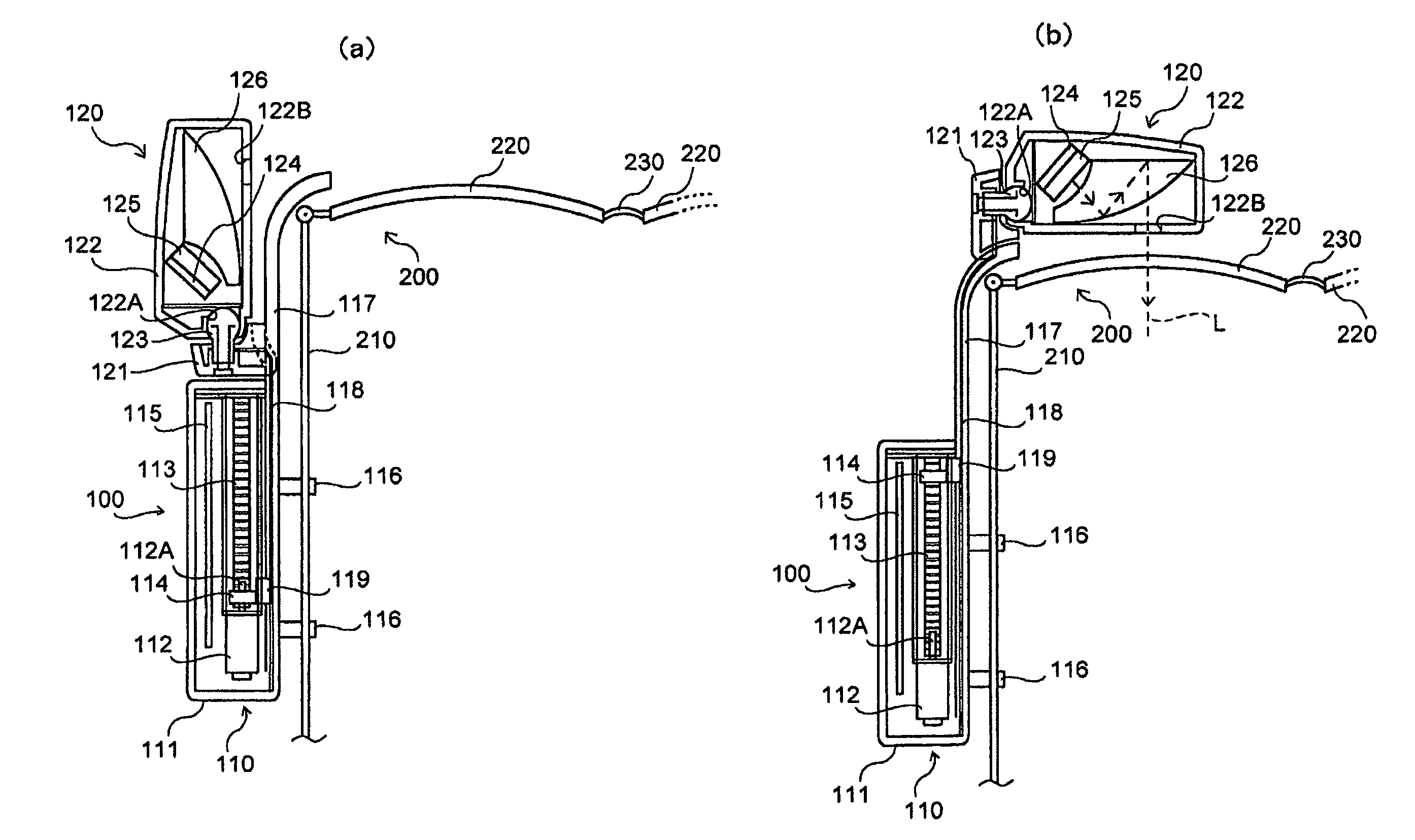
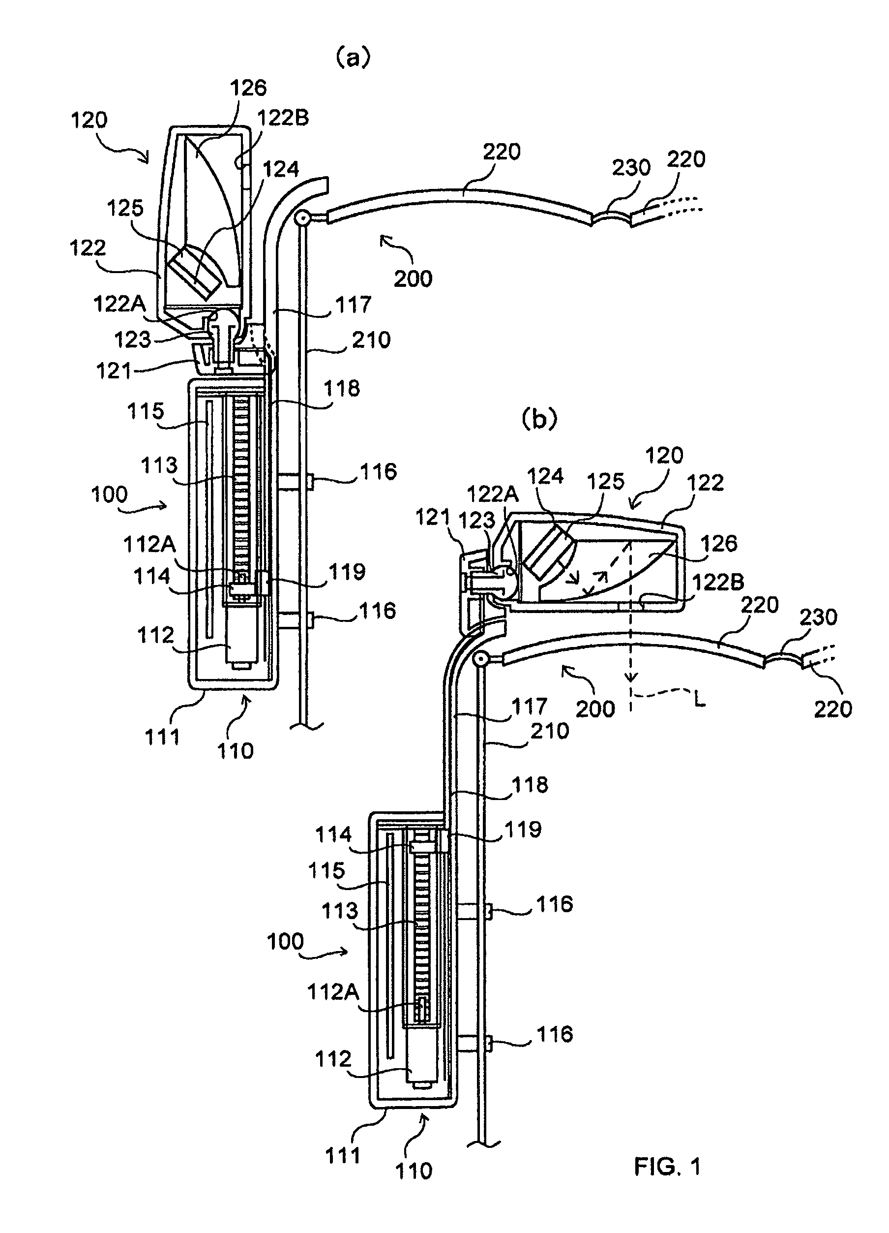
[0041]An image display device 100 of the present invention is structured as shown in FIG. 1. What is depicted by a reference numeral 200 in the figure is a pair of glasses to which the image display device 100 is attached.

[0042]The pair of glasses 200 comprises temples 210, lenses 220, and a bridge 230. There are two temples 210 and two lenses 220. There is only one bridge 230 and it connects the lenses 220. The temples 210 are for holding the glasses 200 in place on the head of a user. The glasses...


PUM


Abstract

To improve a small image display device of the type to be attached to glasses so that positioning thereof can be made easily during use.An image display device 100 comprises a body assembly 110 which can be fixed to a temple 210 of glasses 200, and an image display section 120 adapted to move from a standby position that is located close to the body assembly 110 to a service position just in front of lenses 220. The service position for the image display section 120 is previously determined, and the image display section 120 is automatically moved from the standby position to the service position. This allows the image display section 120 to be positioned at a proper position. The image display section 120 contains a display 125 and a free curved surface prism 126 therein. A user can view images enlarged from the images produced on the display 125 when the image display section 120 is at the service position.

Description

TECHNICAL FIELD[0001]The present invention relates to a small head mounted display device which can be used while being worn on a part of the body such as the head.BACKGROUND OF THE INVENTION[0002]Head mounted displays (HMDs), which are used while worn on a part of the body such as the head to place a video screen in front of each eye of the user, find applications in various fields including the field of virtual reality. Typical HMDs are designed to block out outside light and force the user to see only the HMD's pictures. It usually has a shape of a frame of goggles or large glasses. With an HMD used, the user can view images irrespective of the direction he or she faces but then again it gives the user visual isolation from the surrounding environment.[0003]In recent years, small image display devices have been proposed that allow users to view images as well as the surrounding environment by means of presenting the images in a certain part of the field of vision.[0004]The image ...

Claims


Application Information

Patent Timeline
Patent Type & Authority Patents(United States)
IPC IPC(8): G09G5/00
CPCG02B27/0176G02B2027/0156
Inventor YAMAMOTO, MASAO
Owner SCALAR CORP
Why Eureka
Try Eureka