Magnetic head for perpendicular magnetic recording with shield around main pole

a perpendicular magnetic and recording technology, applied in the direction of magnetic recording heads, data recording, instruments, etc., can solve the problems of difficult for the two side shields to satisfactorily capture, difficult for the two shorting shields to direct much magnetic flux to the two return poles, and difficult for the first return pole to satisfactorily function as a shield. to achieve the effect of enhancing the function of the shield

Active Publication Date: 2013-07-23
HEADWAY TECH INC +1
View PDF30 Cites 38 Cited by
  • Summary
  • Abstract
  • Description
  • Claims
  • Application Information

AI Technical Summary

Benefits of technology

[0013]It is an object of the present invention to provide a magnetic head for perpendicular magnetic recording that has a shield provided around a main pole and is configured to enhance the function of the shield.
[0022]The magnetic head for perpendicular magnetic recording of the present invention includes the shield having an end face that is located in the medium facing surface to wrap around the end face of the main pole. The shield includes the bottom shield, the first and second side shields, and the top shield. The magnetic head of the present invention further includes the first return path section magnetically connected to the bottom shield, and the second return path section that magnetically couples the top shield and the main pole to each other. The first return path section includes the yoke layer, and further includes the first coupling layer and the second coupling layer that magnetically couple the bottom shield and the yoke layer to each other. In a cross section that intersects the end face of the main pole located in the medium facing surface and that is perpendicular to the medium facing surface and the top surface of the substrate, the yoke layer is greater than the bottom shield in length in the direction perpendicular to the medium facing surface, and each of the first and second coupling layers is greater than the bottom shield and smaller than the yoke layer in length in the direction perpendicular to the medium facing surface. Consequently, according to the present invention, it is possible for the shield to capture much magnetic flux, and it is also possible to bring the bottom shield and the main pole into sufficiently close proximity to each other. As a result, it becomes possible to enhance the function of the shield.
[0023]According to the present invention, in the medium facing surface, the distance between the first and second side parts of the main pole and the distance between the first and second sidewalls of the two side shields may both decrease with increasing proximity to the top surface of the substrate. With such a configuration, according to the present invention, it becomes possible to enhance the function of the two side shields.

Problems solved by technology

Such a structure is disadvantageous in that it is difficult to bring the first return pole and the main pole into sufficiently close proximity to each other, and it is thus difficult for the first return pole to satisfactorily function as a shield.
Thus, this structure is disadvantageous in that it is difficult for the two side shields to satisfactorily capture a magnetic flux that is produced from the end face of the main pole and expands in the track width direction.
Accordingly, this magnetic head is disadvantageous in that it is difficult for the two shorting shields to direct much magnetic flux to the two return poles.

Method used


Image

  • Magnetic head for perpendicular magnetic recording with shield around main pole
  • Magnetic head for perpendicular magnetic recording with shield around main pole
  • Magnetic head for perpendicular magnetic recording with shield around main pole

Examples


first embodiment

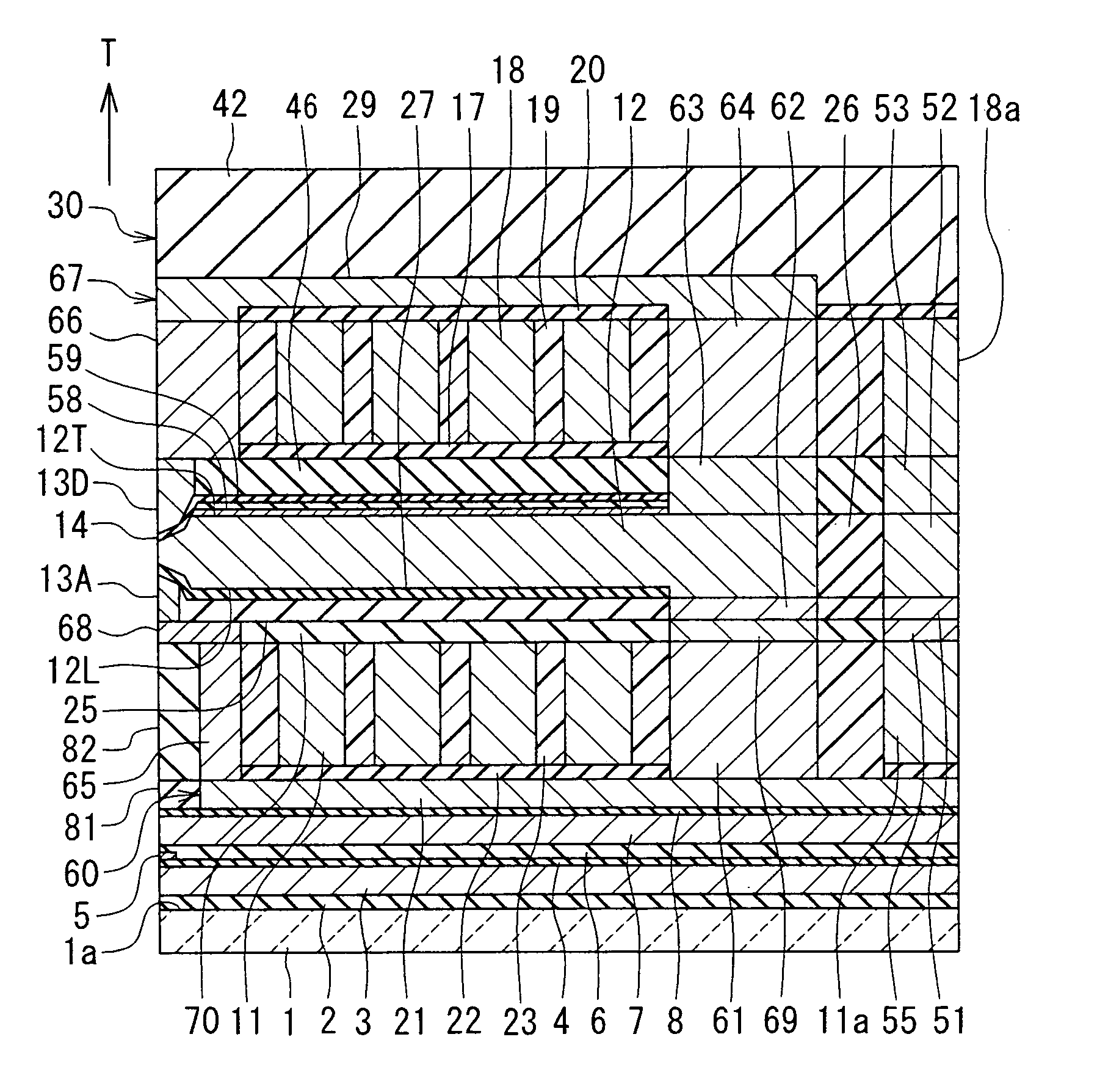
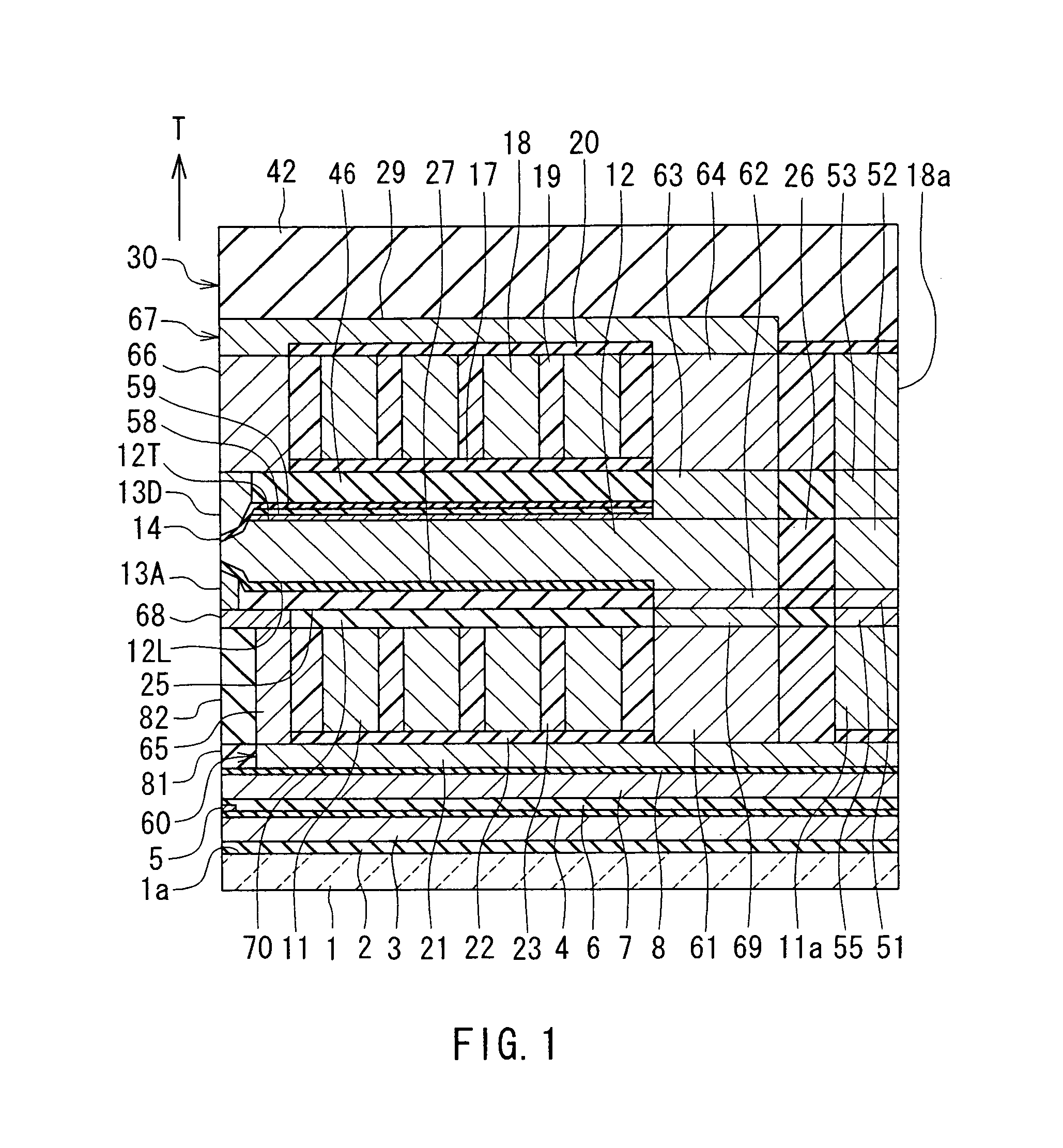
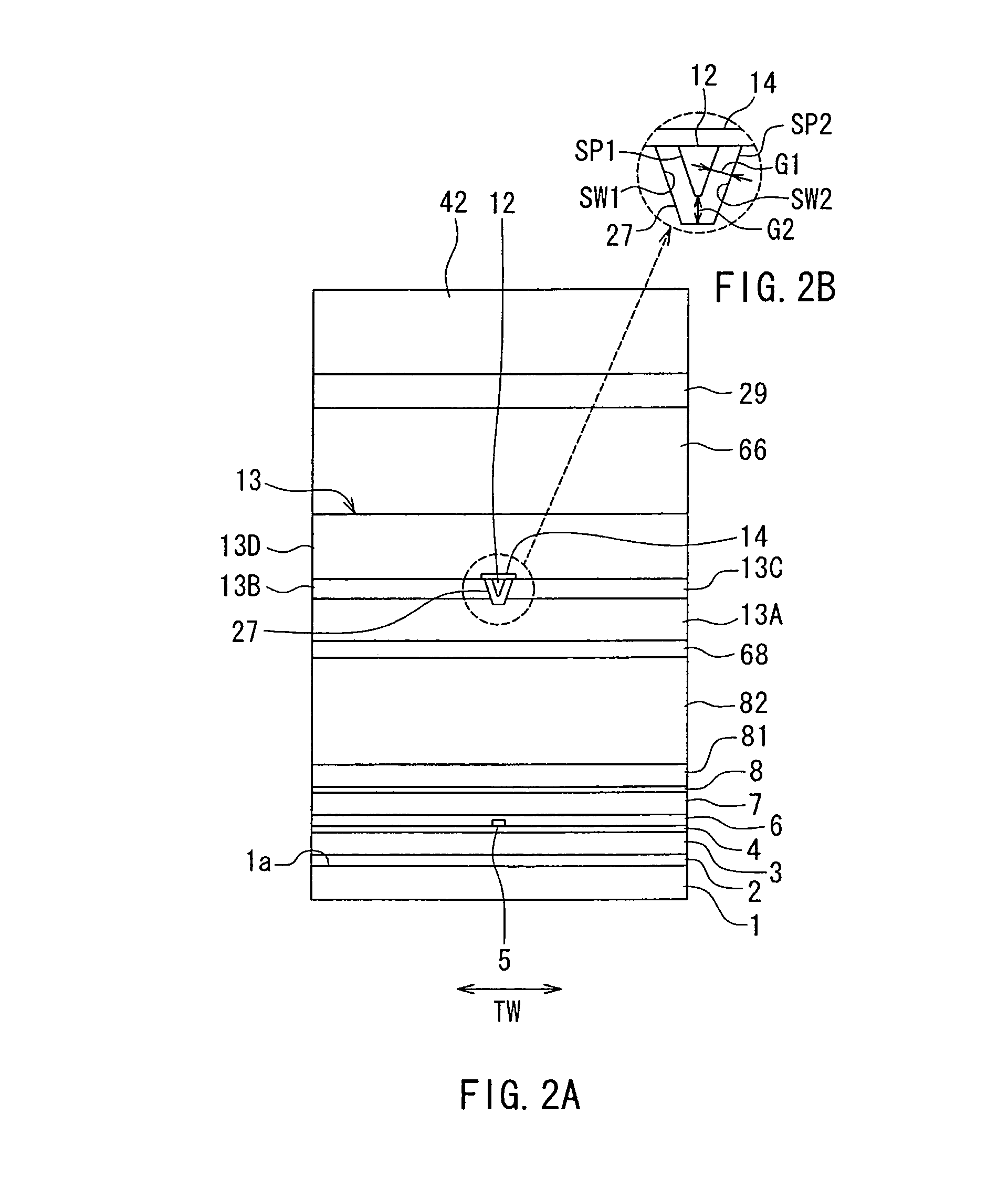
[0052]Embodiments of the present invention will now be described in detail with reference to the drawings. First, reference is made to FIG. 1 to FIG. 5 to describe the configuration of a magnetic head according to a first embodiment of the invention. FIG. 1 is a cross-sectional view of the magnetic head according to the present embodiment. Note that FIG. 1 shows a cross section perpendicular to the medium facing surface and the top surface of the substrate. The arrow with the symbol T in FIG. 1 indicates the direction of travel of the recording medium. FIG. 2A is a front view showing the medium facing surface of the magnetic head according to the present embodiment. FIG. 2B is an enlarged explanatory diagram showing part of FIG. 2A. FIG. 3 is a plan view showing a main pole and two side shields of the magnetic head according to the present embodiment. FIG. 4 is a perspective view of a part of the magnetic head according to the present embodiment. FIG. 5 is a perspective view of the ...

second embodiment

[0156]A magnetic head according to a second embodiment of the invention will now be described with reference to FIG. 23. FIG. 23 is a cross-sectional view of the magnetic head according to the present embodiment. FIG. 23 shows a cross section perpendicular to the medium facing surface and the top surface of the substrate, or the main cross section, in particular.

[0157]The magnetic head according to the present embodiment is different from the magnetic head according to the first embodiment in the following respects. In the magnetic head according to the present embodiment, the insulating layer 19 is configured to cover the second portion 18 of the coil. In the present embodiment, the insulating layer 20 of the first embodiment is not provided. The magnetic head according to the present embodiment has a second return yoke layer 80 made of a magnetic material, instead of the coupling layer 66, the second return yoke layer 29 and the coupling layer 64 of the first embodiment. The secon...

third embodiment

[0160]A magnetic head according to a third embodiment of the invention will now be described with reference to FIG. 24. FIG. 24 is a cross-sectional view of the magnetic head according to the present embodiment. FIG. 24 shows a cross section perpendicular to the medium facing surface and the top surface of the substrate, or the main cross section, in particular.

[0161]The magnetic head according to the present embodiment is different from the magnetic head according to the first embodiment in the following respects. In the magnetic head according to the present embodiment, neither the coupling layer 66 nor the second return yoke layer 29 is exposed in the medium facing surface 30. The respective end faces of the coupling layer 66 and the second return yoke layer 29 closer to the medium facing surface 30 are located at a distance from the medium facing surface 30. The magnetic head according to the present embodiment has an insulating layer 41 disposed around the insulating layer 19 a...


PUM

PropertyMeasurementUnit
distanceaaaaaaaaaa
thicknessaaaaaaaaaa
thicknessaaaaaaaaaa

Abstract

A magnetic head includes a shield, and first and second return path sections. The shield has an end face that is located in a medium facing surface to wrap around an end face of a main pole. The shield includes a bottom shield, two side shields, and a top shield. The first return path section includes a yoke layer, and first and second coupling layers that magnetically couple the bottom shield and the yoke layer to each other. The first coupling layer is magnetically connected to the bottom shield. The second coupling layer magnetically couples the first coupling layer to the yoke layer. No end faces of the second coupling layer are exposed in the medium facing surface. The second return path section magnetically couples the top shield and the main pole to each other.

Description

BACKGROUND OF THE INVENTION[0001]1. Field of the Invention[0002]The present invention relates to a magnetic head for perpendicular magnetic recording that is used for writing data on a recording medium by means of a perpendicular magnetic recording system, and more specifically, to a magnetic head for perpendicular magnetic recording that has a shield provided around a main pole.[0003]2. Description of Related Art[0004]The recording systems of magnetic read / write apparatuses include a longitudinal magnetic recording system wherein signals are magnetized in a direction along the plane of the recording medium (the longitudinal direction) and a perpendicular magnetic recording system wherein signals are magnetized in a direction perpendicular to the plane of the recording medium. It is known that the perpendicular magnetic recording system is harder to be affected by thermal fluctuation of the recording medium and capable of providing higher linear recording density, compared with the ...

Claims


Application Information

Patent Timeline
Patent Type & Authority Patents(United States)
IPC IPC(8): G11B5/127
CPCG11B5/1278G11B5/3163G11B5/315G11B5/3116
Inventor SASAKI, YOSHITAKAITO, HIROYUKISATO, KAZUKIIIJIMA, ATSUSHI
Owner HEADWAY TECH INC
Why Eureka
Try Eureka