Method of controlling gear ratio rate of change in continuously variable transmission

a technology of continuously variable transmission and gear ratio, which is applied in the direction of mechanical equipment, instruments, transportation and packaging, etc., can solve the problems of reducing efficiency, jerking or lugging of machines, and components of hydrostatic drive systems not being able to achieve such quick transitions

Active Publication Date: 2013-07-23
CATERPILLAR INC
View PDF25 Cites 2 Cited by
  • Summary
  • Abstract
  • Description
  • Claims
  • Application Information

AI Technical Summary

Problems solved by technology

However, if the operator commands the hydrostatic drive system to accelerate, decelerate, or change directions too quickly, the components of the hydrostatic drive system may not be capable of such quick transitions and, as a result, the machine may jerk or lug.
This sacrifice of smoothness for speed may result in a reduction of efficiency caused by, for example, discomfort and fatigue of the operator and / or spilling a portion of the load.

Method used


Image

  • Method of controlling gear ratio rate of change in continuously variable transmission
  • Method of controlling gear ratio rate of change in continuously variable transmission
  • Method of controlling gear ratio rate of change in continuously variable transmission

Examples


Embodiment Construction

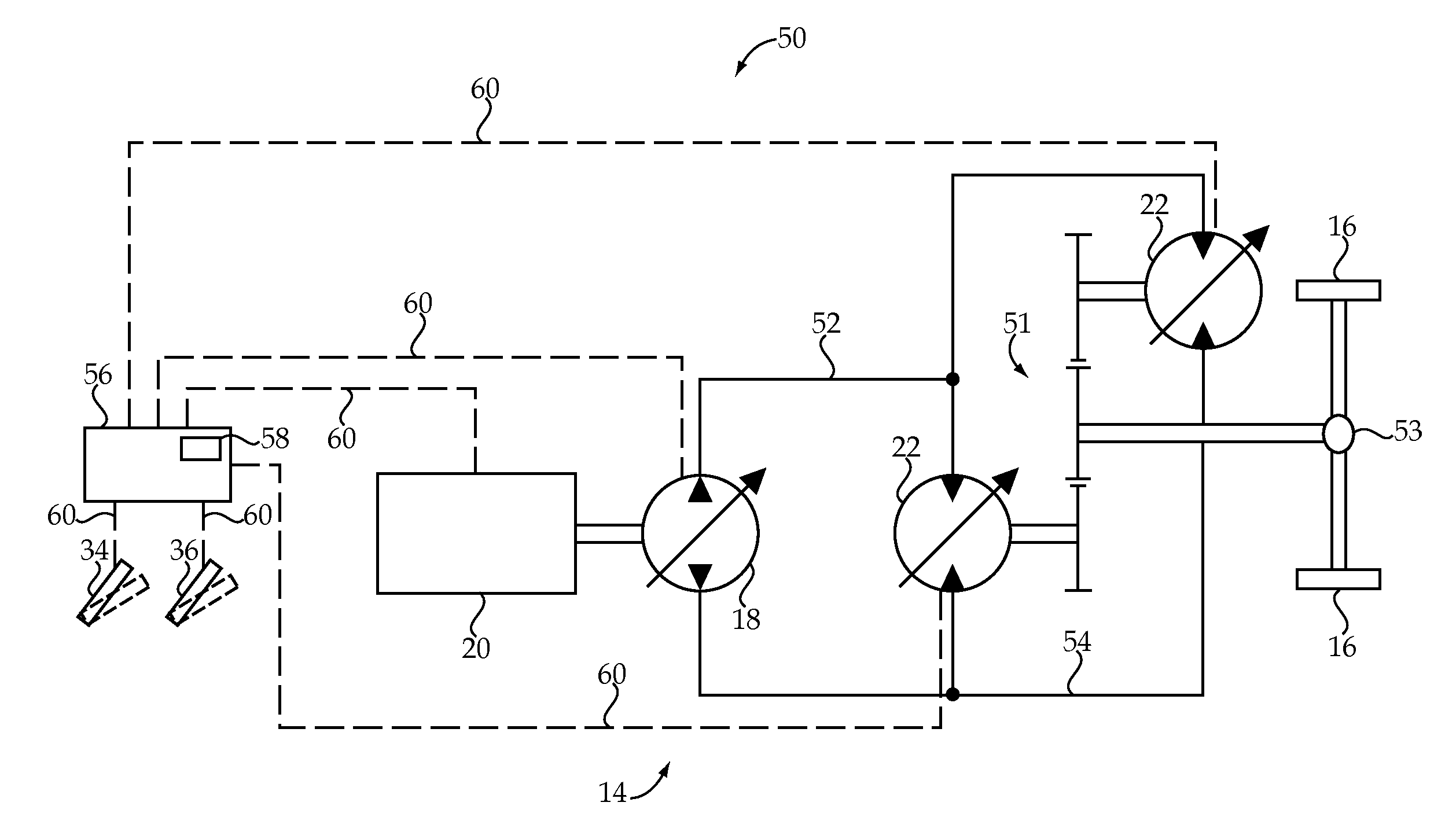
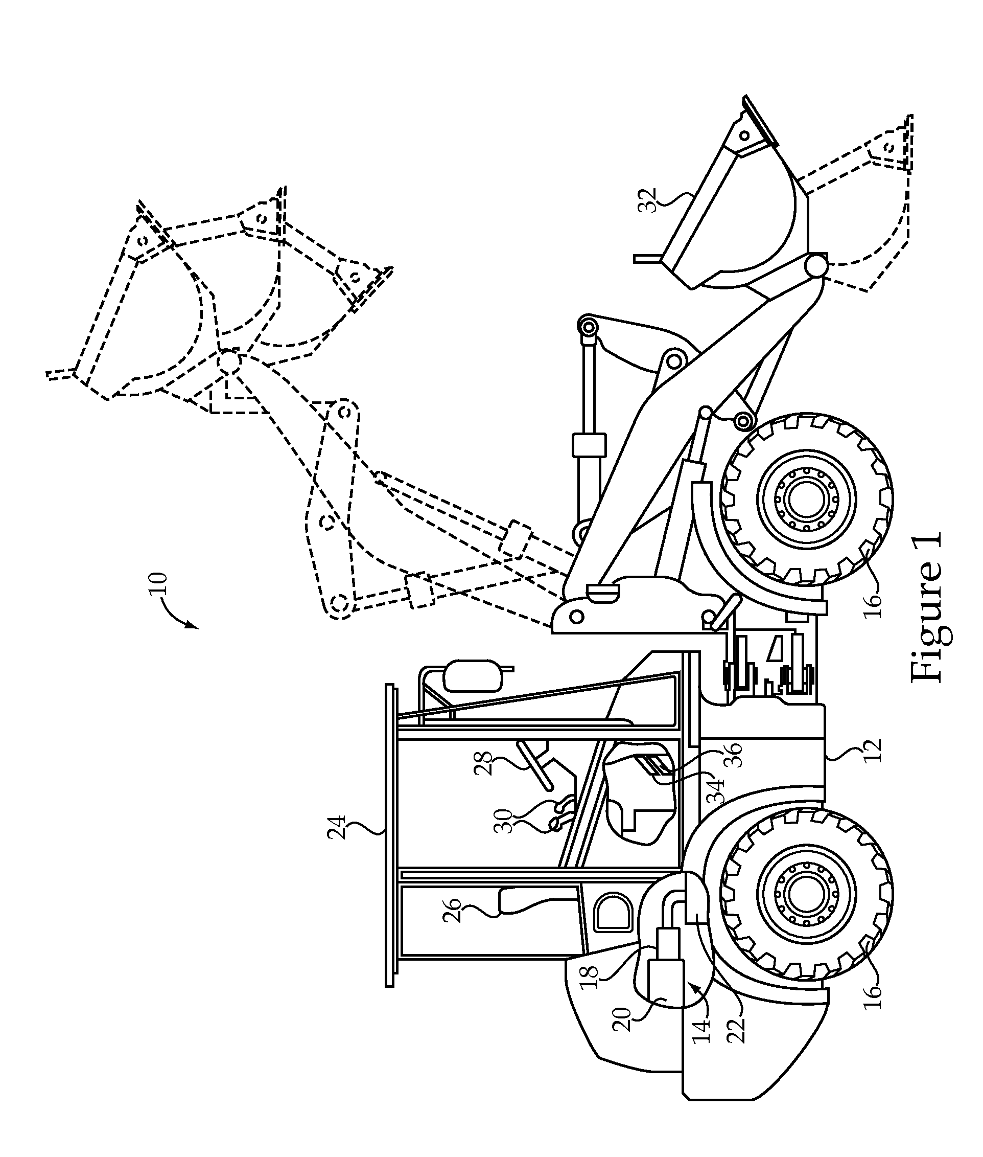
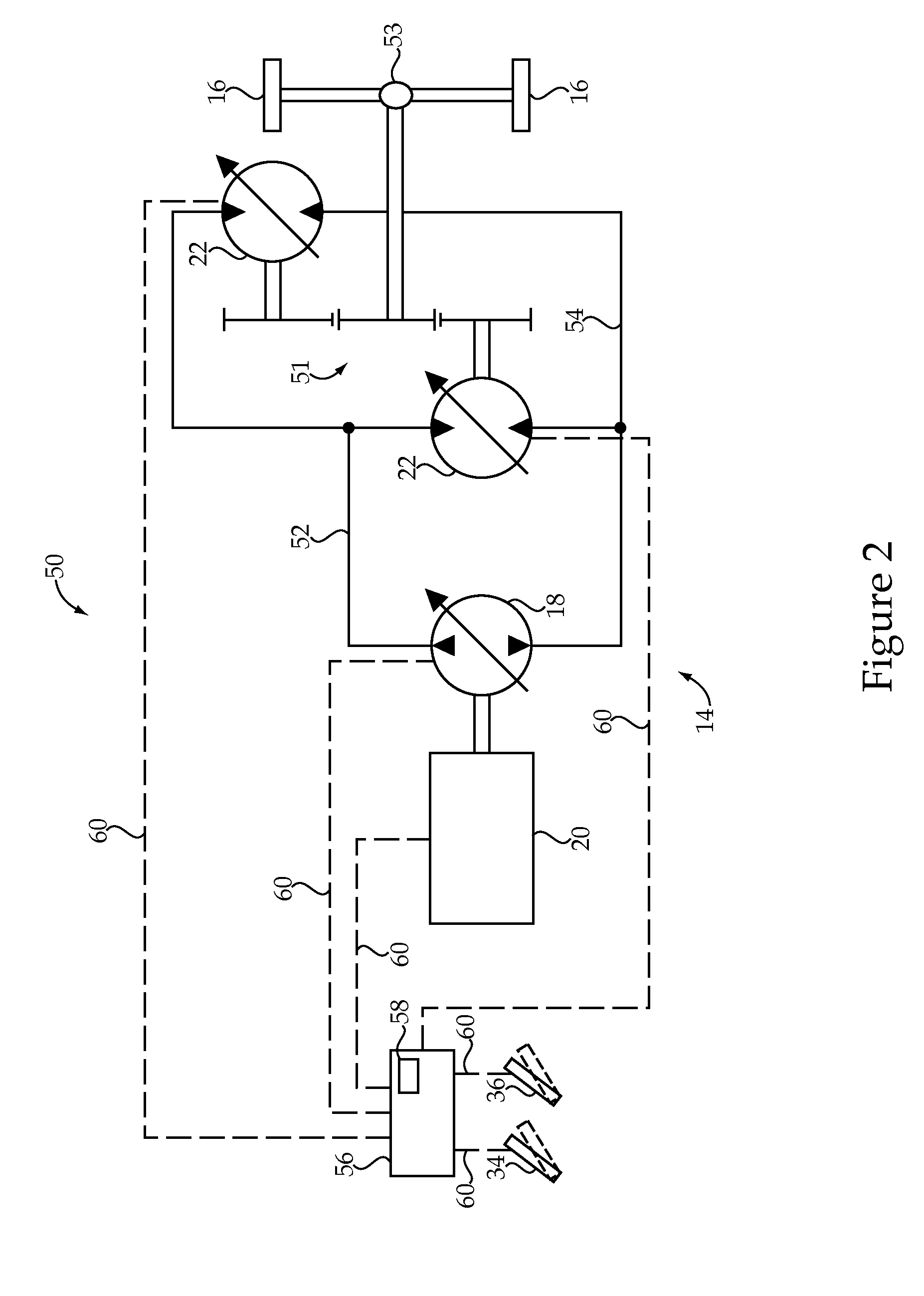
[0021]An exemplary embodiment of a machine 10 is shown generally in FIG. 1. The machine 10 may be a wheel loader, as shown, or any other off-highway or on-highway vehicle having a continuously variable transmission. Although the application is widely applicable to any machine having a continuously variable transmission, a machine having a hydrostatic drive system is shown. As such, machine 10 may also be referenced herein as a hydrostatic drive machine or, more specifically, a hydrostatic drive wheel loader. In the illustrated embodiment, machine 10 generally includes a frame 12 having a hydrostatic drive system 14 supported thereon for driving ground engaging elements 16, such as wheels (shown) or tracks, of the machine 10. A strategy presented herein for controlling the hydrostatic drive system 14 may be widely applicable to a machine having any continuously variable transmission and, therefore, it should be appreciated that the specific embodiments provided are presented for exem...


PUM


Abstract

A method is provided for controlling a gear ratio rate of change in a machine having a continuously variable transmission. The method includes moving an operator input device to a changed position, receiving electronic data indicative of the changed position, and determining a non-limited desired gear ratio based at least in part on the changed position. A maximum gear ratio rate of change corresponding to the changed position is selected from an electronically stored gear ratio rate map. A current desired gear ratio is determined based at least in part on the non-limited desired gear ratio and the maximum gear ratio rate of change. The method also includes changing a commanded gear ratio of the continuously variable transmission to the current desired gear ratio using electronic signals.

Description

TECHNICAL FIELD[0001]The present disclosure relates generally to a control system and method for a machine having a continuously variable transmission, and more particularly to a control system and method for limiting a gear ratio rate of change in the machine.BACKGROUND[0002]Many machines, including off-highway machines, are known to use continuously variable transmissions to drive the ground engaging elements, such as wheels or tracks, of the machine. For example, a hydrostatic drive system commonly includes at least one pump driven by a prime mover, such as an internal combustion engine, of the machine. The pump may be configured to drive one or more sets of motors, which, in turn, power the ground engaging elements of the machine. The pump, and / or motors, may provide variable displacement, such that a fluid flow between the components of the hydrostatic drive system may be adjusted while the machine is running. As a result, direction, speed, and torque of the drive wheels may be...

Claims


Application Information

Patent Timeline
Patent Type & Authority Patents(United States)
IPC IPC(8): G06F7/00
CPCF16H61/462B60W2540/165
Inventor ANDERSON, RANDALL TODDWILL, BRADLEY JOHN
Owner CATERPILLAR INC
Why Eureka
Try Eureka